


50
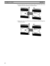
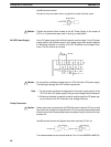
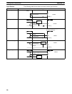
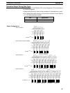
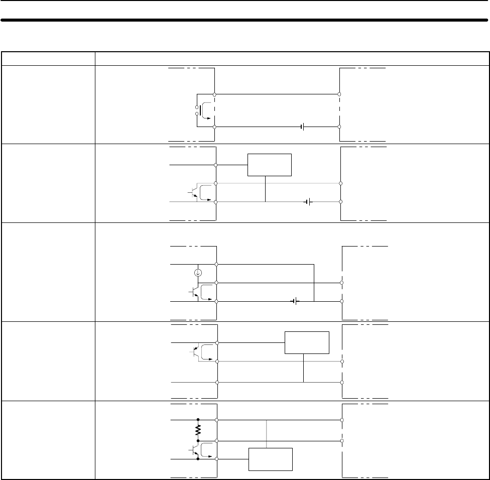
Input Devices The following table shows how to connect various input devices.
Device Circuit diagram
Relay output
IN
COM (+)
Relay
5 mA/12 mA CPM1A
NPN open collector
0 V
+
IN
COM (+)
Sensor
Sensor power
supply
Output
5 mA/12 mA
CPM1A
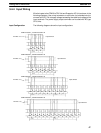
NPN current output
0 V
+
IN
COM (+)
Constant current
circuit
Output
Use the same power supply for
the input and sensor.
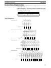
+
5 mA/12 mA
CPM1A
PNP current output
Sensor power
supply
COM (–)
0 V
IN
+
Output
5 mA/12 mA
CPM1A
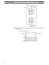
Voltage output
Sensor power
supply
IN
COM (+)
0 V
Output
CPM1A
+
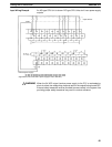
Wiring and Connections
Section 3-4