


61
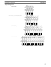
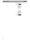
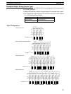
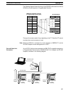
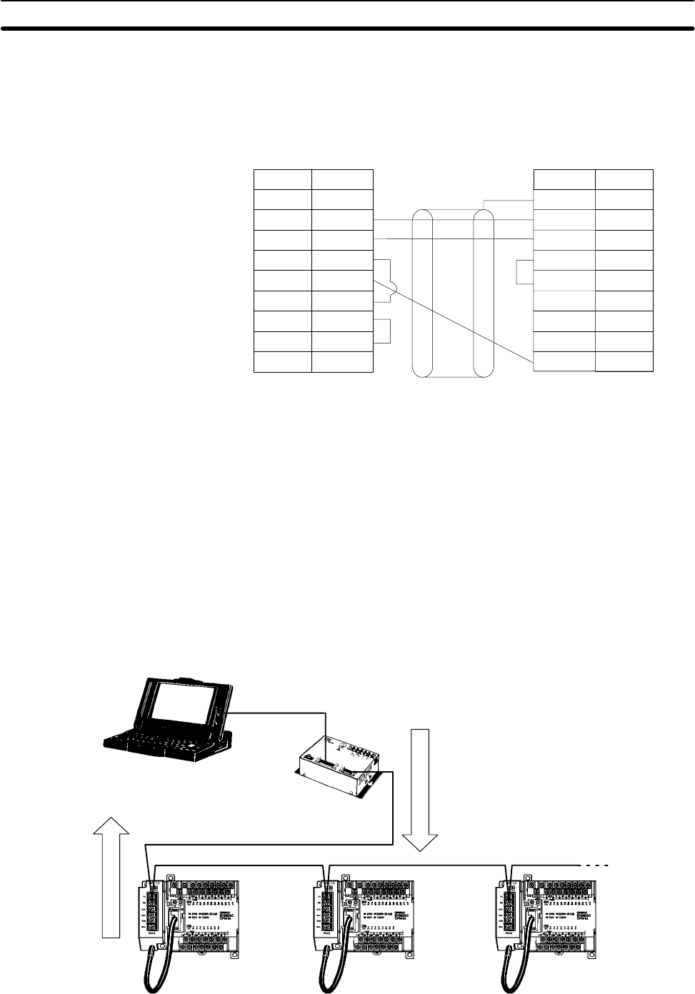
The following diagram shows the wiring in the RS-232C cable used to connect a
CPM1A to a host computer or Programmable Terminal.
IBM PC/AT compatible computer
or Programmable Terminal (9-pin)
RS-232C Adapter
1
2
3
4
5
6
CD
RD
SD
ER
SG
DR
RS
CS
CI
7
8
9
1/Cover
2
3
4
5
6
7
8
9
FG
SD
RD
RS
CS
–
–
SG9
Pin No.Signal
–
Pin No. Signal
The type of connector used will vary depending on the PT. Check the PT manual
to ensure the correct connector is used.
Note When the CPM1A is connected to a host computer or OMRON PT, set the
RS-232C Adapter’s mode setting switch to “HOST.”
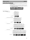
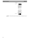
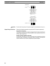
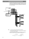
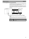
Up to 32 CPU Units can be connected to an IBM PC/AT compatible computer or
a Programmable Terminal with a 3G2A9-AL004-E Link Adapter and RS-422
Adapters, as shown in the following diagram.
CPM1A
CPU Unit
CPM1A
CPU Unit
RS-422
Adapter
RS-422
Adapter
CPM1A
CPU Unit
RS-422
Adapter
Link Adapter
3G2A9-AL004-E
RS-232C cable
RS-422 cable
One-to-N Host Link
Connection
Wiring and Connections
Section 3-4