


62
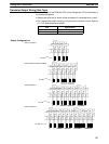
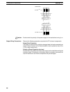
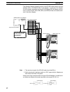
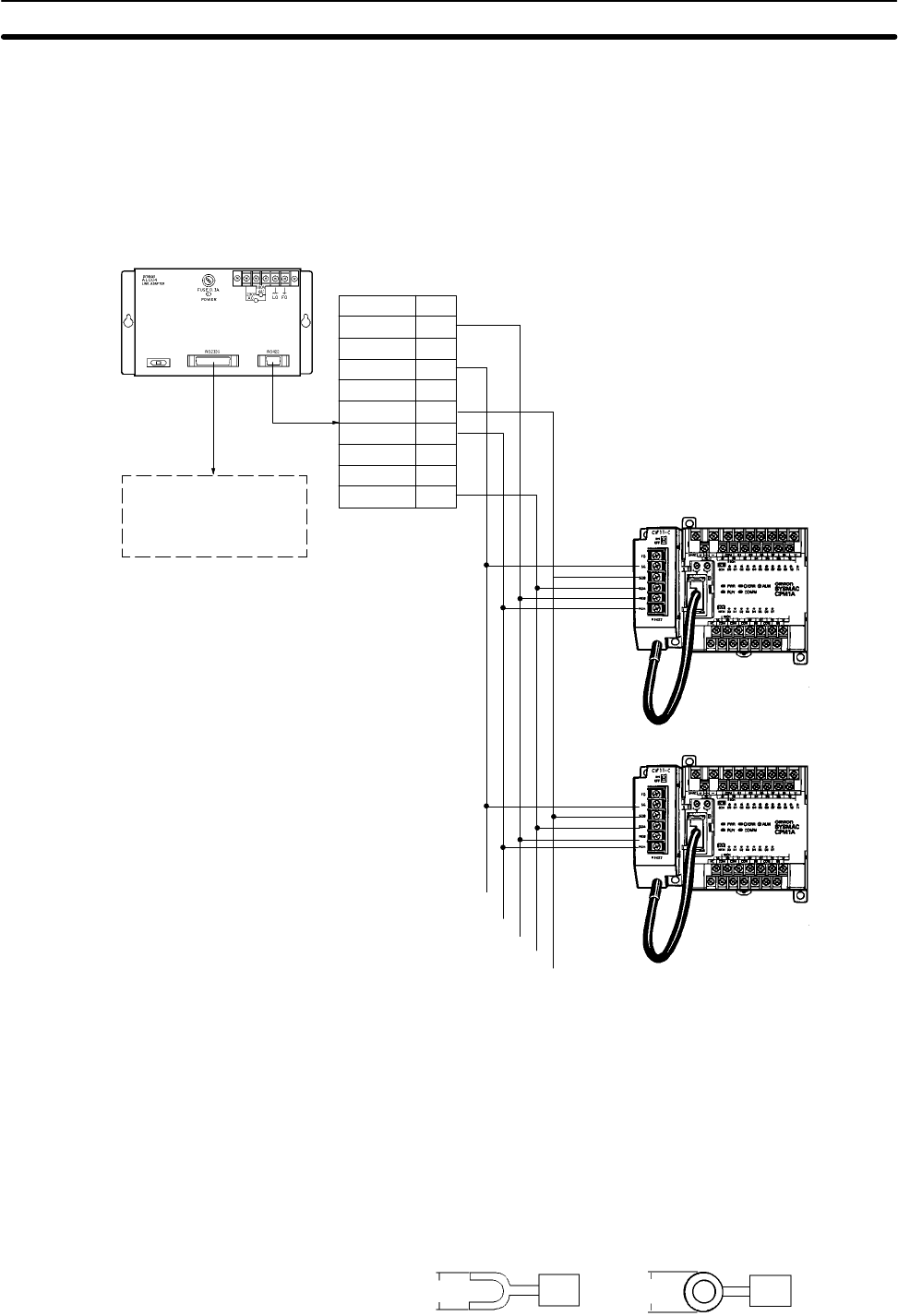
The following diagram shows the wiring in the RS-422 cables used to connect
CPM1A PCs to a 3G2A9-AL004-E Link Adapter. In both the Link Adapter/
RS-422 Adapter connections and the RS-422 Adapter/RS-422 Adapter connec-
tions, connect the SG, RDA, RDB, SDA, and SDB terminals to the same termi-
nals in the other Adapter.
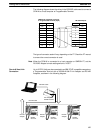
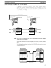
25-pin D-sub Connector
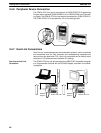
Use a straight RS-232C
cable to connect to the
host computer’s
RS-232C port.
9-pin D-sub Connector
Signal
Pin no.
1
2
3
4
5
6
7
8
9
RDB
–
SG
–
SDB
RDA
FG
–
SDA
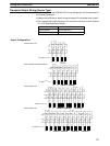
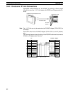
3G2A9-AL004-E Link Adapter
RS-422 Adapter
SG
RDA
RDB
SDA
SDB
CPM1A CPU Unit
Note 1. The maximum length of the RS-422 cable should be 500 m.
2. Set the termination resistance switch to “ON” (upper side) for Adapters on
both ends of the Host Link system.
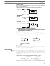
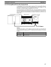
Always use crimp connectors when wiring the RS-422 Adapters. Use M3 termi-
nal screws and tighten the screws securely to the torque of 0.5 N S m.
6.2 mm max.
Fork terminal
6.2 mm max.
Ring terminal
Wiring and Connections
Section 3-4