


40
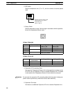
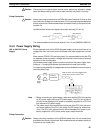
CPM1A-30CDR-j/30CDT-D/30CDT1-D and
CPM1A-40CDR-j/40CDT-D/40CDT1-D
CPU Unit
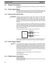
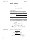
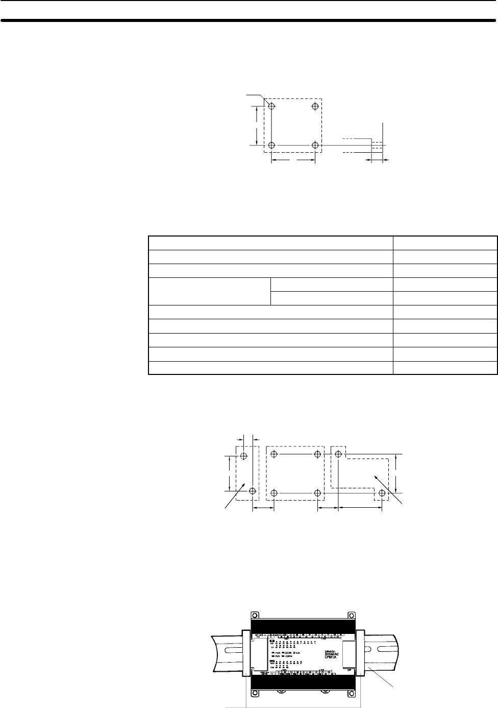
Four, M4 holes
100 mm
8 mm
A
Use M4 dia. x 15 screws.
The width (A) between the mounting holes depends on the CPM1A model.
Model number Width (A)
CPM1A-30CDR-j/30CDT-D/30CDT1-D CPU Unit
120 mm
CPM1A-40CDR-j/40CDT-D/40CDT1-D CPU Unit
140 mm
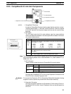
Expansion I/O Unit
CPM1A-20EDj
76 mm
CPM1A-8Ej
56 mm
Analog I/O Unit 56 mm
CompoBus/S I/O Link Unit 56 mm
RS-232C Adapter 21 mm
RS-422 Adapter 21 mm
Temperature Sensor Unit 76 mm
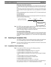
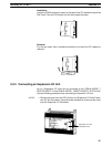
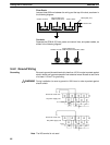
Allow 10 to 15 mm between the Units when installing an Expansion Unit, Expan-
sion I/O Unit, or Communications Adapter next to the CPU Unit, as shown below.
Expansion Unit or
Expansion I/O Unit
Communications
Adapter
CPU Unit
10 to
15 mm
10 to
15 mm
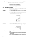
100 mm81 mm
21 mm
A
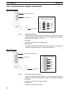
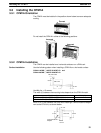
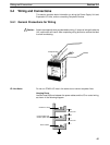
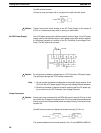
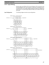
DIN Track Installation The CPM1A can be installed on a 35-mm DIN Track.
End Plates
(PFP-M)
DIN Track
PFP-100N (1 m)
PFP-50N (50 cm)
PFP-100N2 (1 m)
Installing the CPM1A
Section 3-3