!
44
Floor Ducts
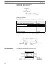
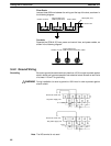
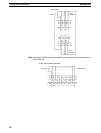
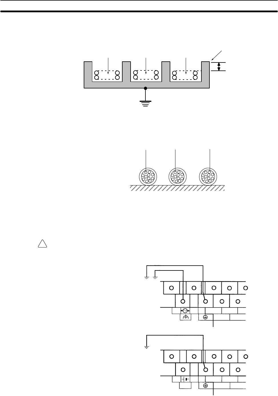
Leave at least 200 mm between the wiring and the top of the duct, as shown in
the following diagram.
200 mm min.
Metal plate (iron)
CPM1A I/O lines
Control cables and
CPM1A power lines
Power cables
Conduits
Separate the CPM1A I/O lines, power and control lines, and power cables, as
shown in the following diagram.
CPM1A I/O lines
Control cables and
CPM1A power lines
Power cables
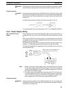
3-4-2 Ground Wiring
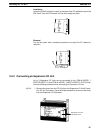
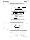
Grounding Be sure to ground the earth terminal to less than 100 Ω in order to protect against
electric shock and incorrect operation from electrical noise. Be sure to use a wire
of at least 1.25 mm
2
for grounding.
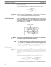
WARNING During installation, be sure to ground to 100 Ω max in order to protect against
electric shock.
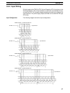
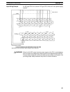
Ground to 100 Ω max.
Ground to 100 Ω max.
AC power supply unit
DC power supply unit
L1
L2/N
0 CH
00 02
01
COM
COM
00 02
01
0 CH
NC
24 VDC
+ –
100 to 240 VAC
Note The NC terminal is not used.
Wiring and Connections
Section 3-4


