


!
6
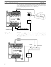
Input Interrupts The CPM1A-10CDR-j/10CDT-D/10CDT1-D PCs have 2 interrupt input termi-
nals and the CPM1A-20CDR-j/20CDT-D/20CDT1-D, CPM1A-30CDR-j/
30CDT-D/30CDT1-D, and CPM1A-40CDR-j/40CDT-D/40CDT1-D PCs have
4 interrupt input terminals. There are two modes for input interrupts: input inter-
rupt mode and counter mode.
1, 2, 3... 1. When an interrupt occurs in Input Interrupt Mode, the main program is inter-
rupted and the interrupt program is executed immediately, regardless of the
cycle time.
2. In Counter Mode, external input signals are counted at high speed (up to
1 kHz) and an interrupt is generated each time the count reaches the set
value. When an interrupt occurs, the main program is interrupted and the
interrupt program is executed. The set value can be set from 0 to 65,535.
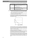
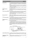
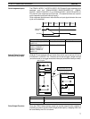
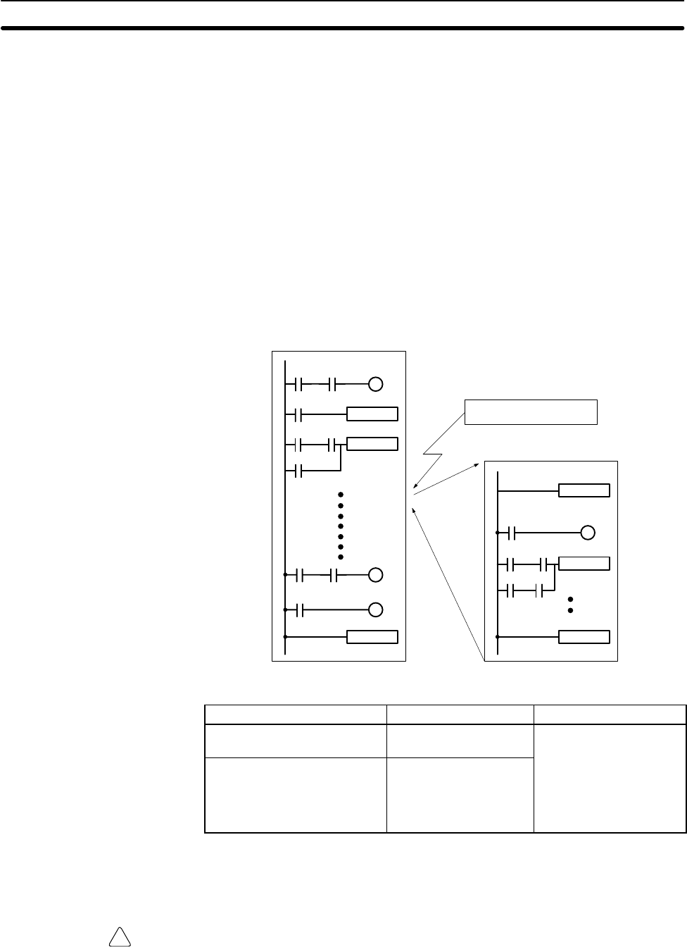
The following diagram shows the program execution when an interrupt occurs.
Main program
Input interrupt
Interrupt program
MOV
ADD
END
SBN00
MOV
RET
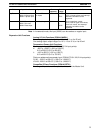
PC model Input bits Response time
CPM1A-10CDR-j/10CDT-D/
10CDT1-D
IR 00003 to IR 00004
0.3 ms
(1 kHz in Counter Mode)
CPM1A-20CDR-j/20CDT-D/
20CDT1-D/30CDR-j/
30CDT-D/30CDT1-D/
40CDR-j/40CDT-D/
40CDT1-D
IR 00003 to IR 00006
Note When not using as interrupt input terminals, the input bits IR 00003 to IR 00006
can be used as normal input terminals.
Caution Although IORF(97) can be used in interrupt subroutines, you must be careful of
the interval between IORF(97) executions. If IORF(97) is executed too frequent-
ly, a fatal system error may occur (FALS 9F), stopping operation. The interval
between executions of IORF(97) should be at least 1.3 ms + total execution time
of the interrupt subroutine.
CPM1A Features and Functions Section 1-1