


47
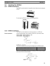
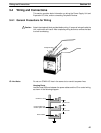
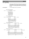
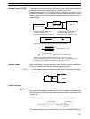
3-4-4 Input Wiring
Wire the inputs to the CPM1A’s CPU Unit and Expansion I/O Unit as shown in the
following diagrams. Use crimp connectors or solid wire (not stranded wire) to
connect to the PC. Do not apply voltages exceeding the rated input voltage to the
input terminals. The power supply output terminals can be used with AC-type
CPU Units.
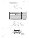
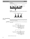
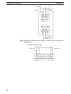
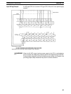
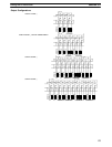
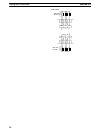
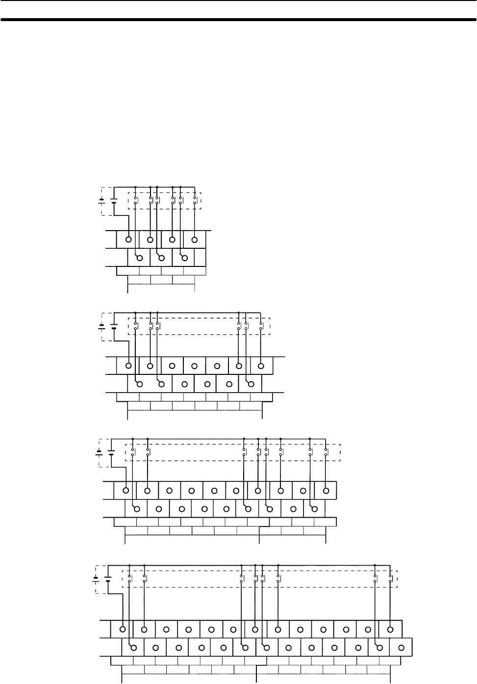
Input Configuration The following diagrams show the input configurations.
24 VDC
+10%
/
–15%
Input devices
Input devices
Input devices
Input devices
CPM1A-10CDR-j/10CDT-D/10CDT1-D
CPM1A-20CDR-j/20CDT-D/20CDT1-D
CPM1A-30CDR-j/30CDT-D/30CDT1-D
CPM1A-40CDR-j/40CDT-D/40CDT1-D
24 VDC
+10%
/
–15%
24 VDC
+10%
/
–15%
24 VDC
+10%
/
–15%
COM
00
02
01
0 CH
04
03 05
COM
00
02
01
0 CH
04
03 05
08
07 09
06 10
11
COM
00
02
01
0 CH
04
03 05
08
07 09
06 10
11
00
02
01
1 CH
04
03 05
COM
00
02
01
0 CH
04
03 05
08
07 09
06 10
11
00
02
01
1 CH
04
03 05
08
07 09
06 10
11
Wiring and Connections
Section 3-4