


29
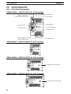
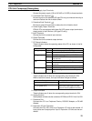
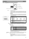
CPU Unit Component Descriptions
1, 2, 3... 1. Power Supply Input Terminals
Connect the power supply (100 to 240 VAC or 24 VDC) to these terminals.
2. Functional Earth Terminal ( )
Be sure to ground this terminal (AC-type PCs only) to enhance immunity to
noise and reduce the risk of electric shock.
3. Protective Earth Terminal ( )
Be sure to ground this terminal to reduce the risk of electric shock.
4. Power Supply Output Terminals
CPM1A PCs are equipped with these 24-VDC power output terminals to
supply power to input devices. (AC-type PCs only.)
5. Input Terminals
Connect the Unit to external input devices.
6. Output Terminals
Connect the Unit to external output devices.
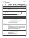
7. PC Status Indicators
These indicators show the operating status of the PC, as shown in the fol-
lowing table.
Indicator Status Meaning
PWR (green)
ON Power is being supplied to the PC.
OFF Power isn’t being supplied to the PC.
RUN (green)
ON The PC is operating in RUN or MONITOR mode.
OFF The PC is in PROGRAM mode or a fatal error
has occurred.
ERR/ALARM
ON A fatal error has occurred. (PC operation stops.)
(red)
Flashing A non-fatal error has occurred. (PC operation
continues.)
OFF Indicates normal operation.
COMM (orange)
ON Data is being transferred via the Peripheral Port.
OFF Data isn’t being transferred via the Peripheral
Port.
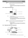
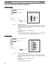
8. Input Indicators
These indicators are lit when the corresponding input terminal is ON.
When a fatal error occurs, the input indicators change as follows:
Fatal error Input indicators
CPU Unit error or I/O bus error Turn OFF.
Memory error, no END instruction
error, or system error
The indicators will change with the
status of the input signal, but input
status will not be updated in memory.
9. Output Indicators
These indicators are lit when the corresponding output terminal is ON.
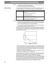
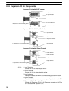
10. Analog Controls
Setting these controls sets the contents of IR 250 and IR 251 from 0 to 200.
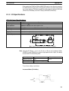
11. Peripheral Port
Connects the PC to a Peripheral Device, RS-232C Adapter, or RS-422
Adapter.
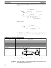
12. Expansion I/O Unit Connector
Connects the PC’s CPU Unit to an Expansion I/O Unit to add another 12
input points and 8 output points. Up to 3 Expansion I/O Units can be con-
nected.
Unit Components
Section 2-2