


!
33
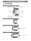
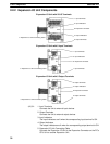
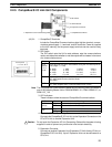
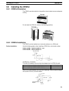
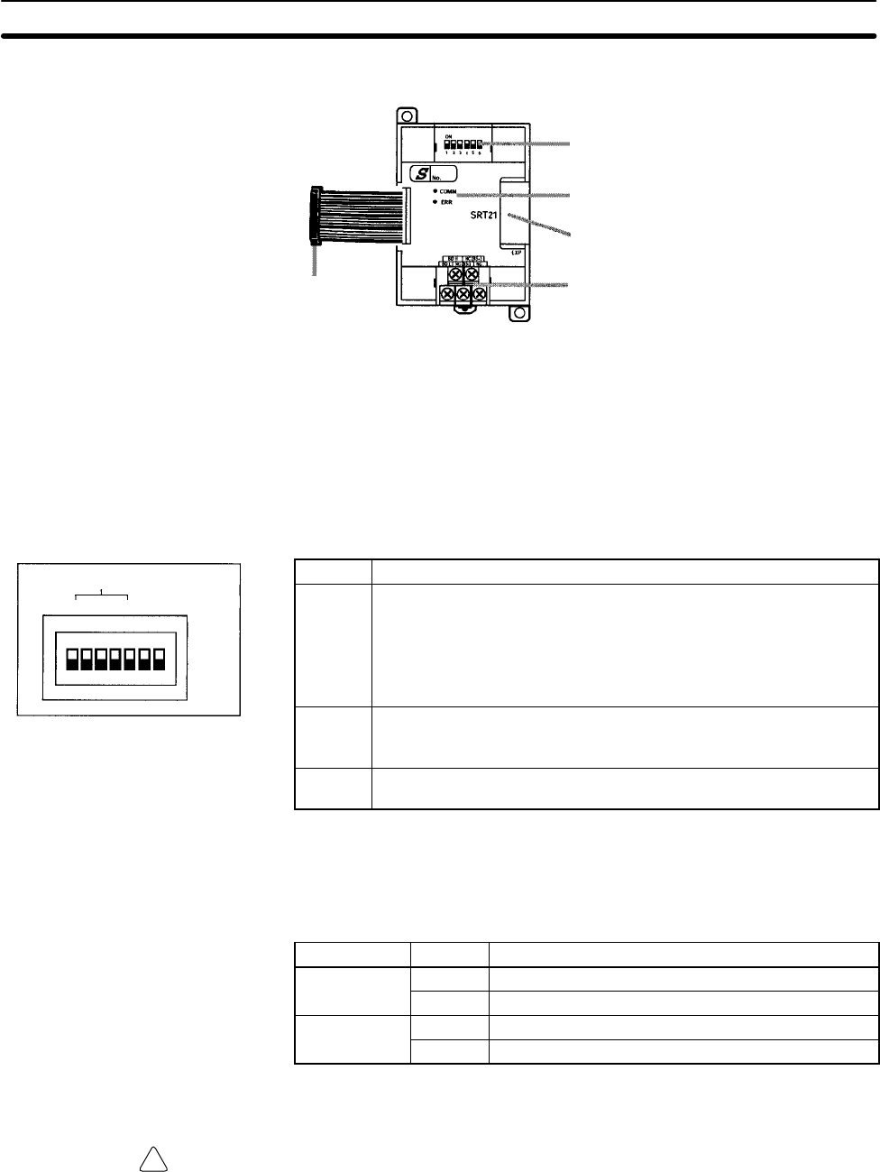
2-2-5 CompoBus/S I/O Link Unit Components
1. CompoBus/S terminals
4. Expansion I/O Unit Connecting Cable
2. DIP switch
5. Expansion connector
3. LED indicators
1, 2, 3... 1. CompoBus/S Terminals
Include the CompoBus/S communications data high/low terminal, commu-
nications power supply +/– terminals, and NC terminals. Power is supplied
to the Unit internally, so the power supply terminals can be used as relay
terminals.
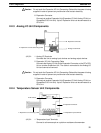
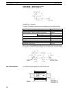
2. DIP Switch
The DIP switch sets the Unit’s node address, sets the communications
mode, and determines whether or not the outputs will be cleared in the event
of a communications error.
Pin(s) Function
1 to 4
(labeled
1, 2, 4,
and 8)
These pins set the Unit’s node address using the DIP switch pins as
binary digits. (1 = ON)
0: 0000 1: 0001 2: 0010 3: 0011
4: 0100 5: 0101 6: 0110 7: 0111
8: 1000 9: 1001 10: 1010 11: 1011
12: 1100 13: 1101 14: 1110 15: 1111
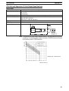
DR ON: Long-distance Communications Mode
OFF:High-speed Communications Mode
(See note.)
HOLD ON: Retain outputs when a communications error occurs.
OFF:Clear outputs when a communications error occurs.
Note The Long-distance Communications Mode can be used only when connected to
one of the following Master Units: C200HW-SRM21-V1, CQM1-SRM21-V1, or
SRM1-C0j-V2.
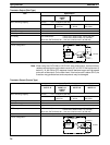
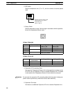
3. LED Indicators
These indicators show the status of CompoBus/S communications.
Indicator Status Meaning
COMM
ON Communications in progress.
(yellow)
OFF Communications error or stopped.
ERR
ON A communications error has occurred.
(red)
OFF Indicates normal or no communications.
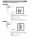
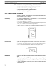
4. Expansion I/O Unit Connecting Cable
Connects the CompoBus/S I/O Link Unit to the Expansion Connector on the
PC’s CPU Unit or another Expansion Unit.
Caution Do not touch the Expansion I/O Unit Connecting Cable while the power is being
supplied in order to prevent any malfunction due to static electricity.
5. Expansion Connector
Connects to another Expansion Unit (Expansion I/O Unit, Analog I/O Unit, or
CompoBus/S I/O Link Unit). Up to 3 Expansion Units can be connected to a
CPU Unit.
Unit Components
Section 2-2
NODE ADDRESS
1
2
4
8
DR
HOLD
SW1
ON