


12
13
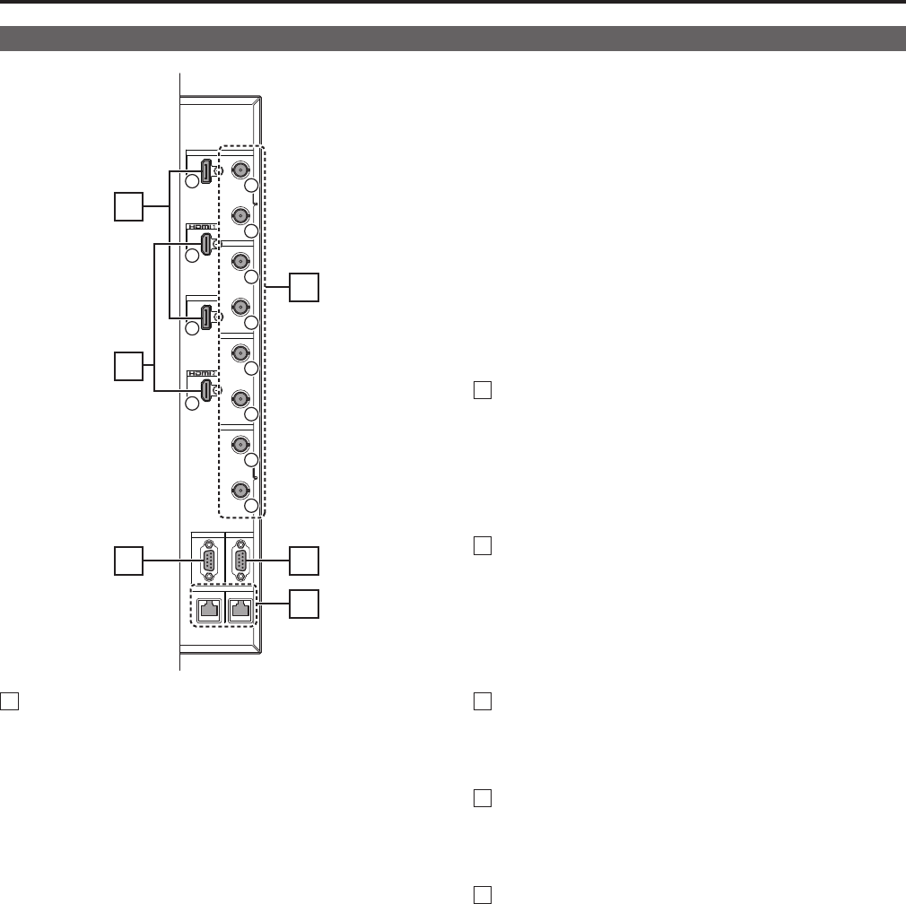
Names and Functions of Parts (Continued)
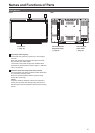
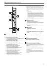
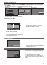
Connector Section (Right Side Panel)
OUT
IN
OUT
IN
RS-485
DisplayPort 1
DisplayPort 2
3G SDI 4
3G SDI 3
IN
OUT
3G SDI 2
IN
OUT
3G SDI 1
RS-232CGPI
IN OUT
6
1
1
5
2
6
3
7
4
8
2
2
1
4
1
5
2
3
1
SDI connectors
A SDI1 (3G/HD) input connector (BNC)
This is an SDI input connector. (It is compatible with 3G-
SDI and 3G/HD automatic switching.)
B SDI2 (3G/HD) input connector (BNC)
This is an SDI input connector. (It is compatible with 3G-
SDI and 3G/HD automatic switching.)
C SDI3 (3G/HD) input connector (BNC)
This is an SDI input connector. (It is compatible with 3G-
SDI and 3G/HD automatic switching.)
D SDI4 (3G/HD) input connector (BNC)
This is an SDI input connector. (It is compatible with 3G-
SDI and 3G/HD automatic switching.)
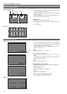
E SDI1 active through output connector (BNC)
This connector outputs SDI1 input as is.
•The SD-SDI signal is not displayed but it is output.
F SDI2 active through output connector (BNC)
This connector outputs SDI2 input as is.
•The SD-SDI signal is not displayed but it is output.
G SDI3 active through output connector (BNC)
This connector outputs SDI3 input as is.
•The SD-SDI signal is not displayed but it is output.
H SDI4 active through output connector (BNC)
This connector outputs SDI4 input as is.
•The SD-SDI signal is not displayed but it is output.
•When this unit is used to connect multiple monitors in a
daisy-chain
*
1
, the screen may become distorted or noise
may occur depending on factors such as the quality of the
original signal, cable length, and number of connected
devices.
*
1
Daisy-chain:
This is a method to connect one signal to multiple
devices in sequence by connecting the through-out of
a signal connected to an input connector of a device to
a second connector of this unit or to an input connector
of a second device, and connecting that through-out to
a third connector of this unit or an input connector of a
third device, and so on.
•Use a 5CFB or equivalent cable to connect to an SDI con-
nector.
2
DisplayPort connectors
A DisplayPort1 signal input connector
Use a double shielded cable to connect to a DisplayPort
connector.
B DisplayPort2 signal input connector
Use a double shielded cable to connect to a DisplayPort
connector.
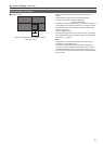
3
HDMI connectors
A HDMI1 signal input connector
Use a double shielded cable to connect to an HDMI con-
nector.
B HDMI2 signal input connector
Use a double shielded cable to connect to an HDMI con-
nector.
4
RS-232C input connector (D-SUB, 9-pin)
External control is possible with an RS-232C signal.
•Use a shielded cable to connect to the RS-232C input con-
nector.
5
GPI input connector (D-SUB, 9-pin)
External control is possible with a GPI signal.
•Use a shielded cable to connect to the GPI input connec-
tor.
6
RS-485 input/output connectors (RJ-45)
External control is possible with an RS-485 signal.
•Use a shielded cable to connect to an RS-485 input/output
connector.
•Make sure that the cable plug is fully inserted in the con-
nector and cannot easily be pulled out.
•A daisy chain connection using the RS-485 input/output
connectors enables the control of multiple monitors (up to
32 monitors).
•Connectaterminator(120Ω)betweenthefirstandsec-
ond pin of the RS-485 OUT terminal on the last monitor in
the chain.