


56
REMOTE Specifications (Continued)
57
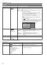
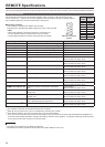
RS-485 Input/Output Connectors
The unit can be operated externally via the RS-485 interface.
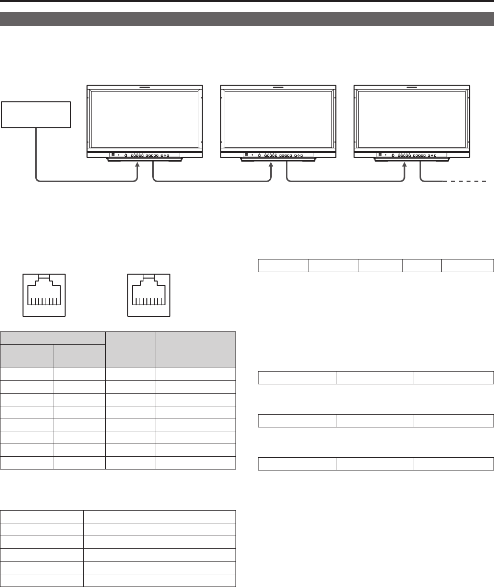
Refer to the figures below for the pin arrangement and connection of the RS-485 input/output connectors.
For details on specific systems using RS-485 input/output connectors, contact your supplier.
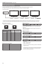
Connection example
External control
device
RS-485 IN RS-485 OUT RS-485 IN RS-485 OUTRS-485 IN RS-485 OUT
•A daisy chain connection using the RS-485 input/output connectors enables the control of multiple monitors (up to 32 monitors).
•Connectaterminatingresistor(120Ω)betweenthefirstandsecondpinoftheOUTconnectoronthelastmonitorinthechain.
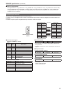
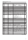
Connectors and signals
Connector: 8-pin RJ-45 connector
IN
87654321
OUT
87654321
Pin number
Signal Description
IN (input)
OUT
(output)
1 3 RXD+ Received data (+)
2 6 RXD- Received data (-)
3 1 TXD+ Send data (+)
4 4 N.C. Not connected
5 5 N.C. Not connected
6 2 TXD- Send data (-)
7 7 N.C. Not connected
8 8 GND Ground
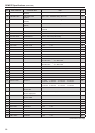
Communication parameters
Synchronous system Asynchronous system
Transfer rate 38 400 bps
Parity EVEN
Data length 8 bit
Stop bit 1 bit
Flow control None
Command format
STX (02h) Header (ID) Command Data EXT (03h)
The header (ID) is 8-bit data.
Set this in the [RS-485 ID SETUP] item of the [SYSTEM CON-
FIG] menu.
When 0 is set in [RS-485 ID SETUP], multiple connected moni-
tors can be controlled.
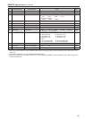
Response formats
1. Setting command response
STX (02h) Command EXT (03h)
2. Query command response
STX (02h) Data EXT (03h)
3. Error response
STX (02h) Error codes EXT (03h)
Error codes
ER001: Invalid command
ER002: Parameter error
When 0 is set in [
RS-485 ID SETUP
], operation is enabled but
responses are not.
After receiving a monitor response command, there should be
a time lag of approx. 200 ms before a command is transmit-
ted from an external control device.