18
On-screen Display (Continued)
19
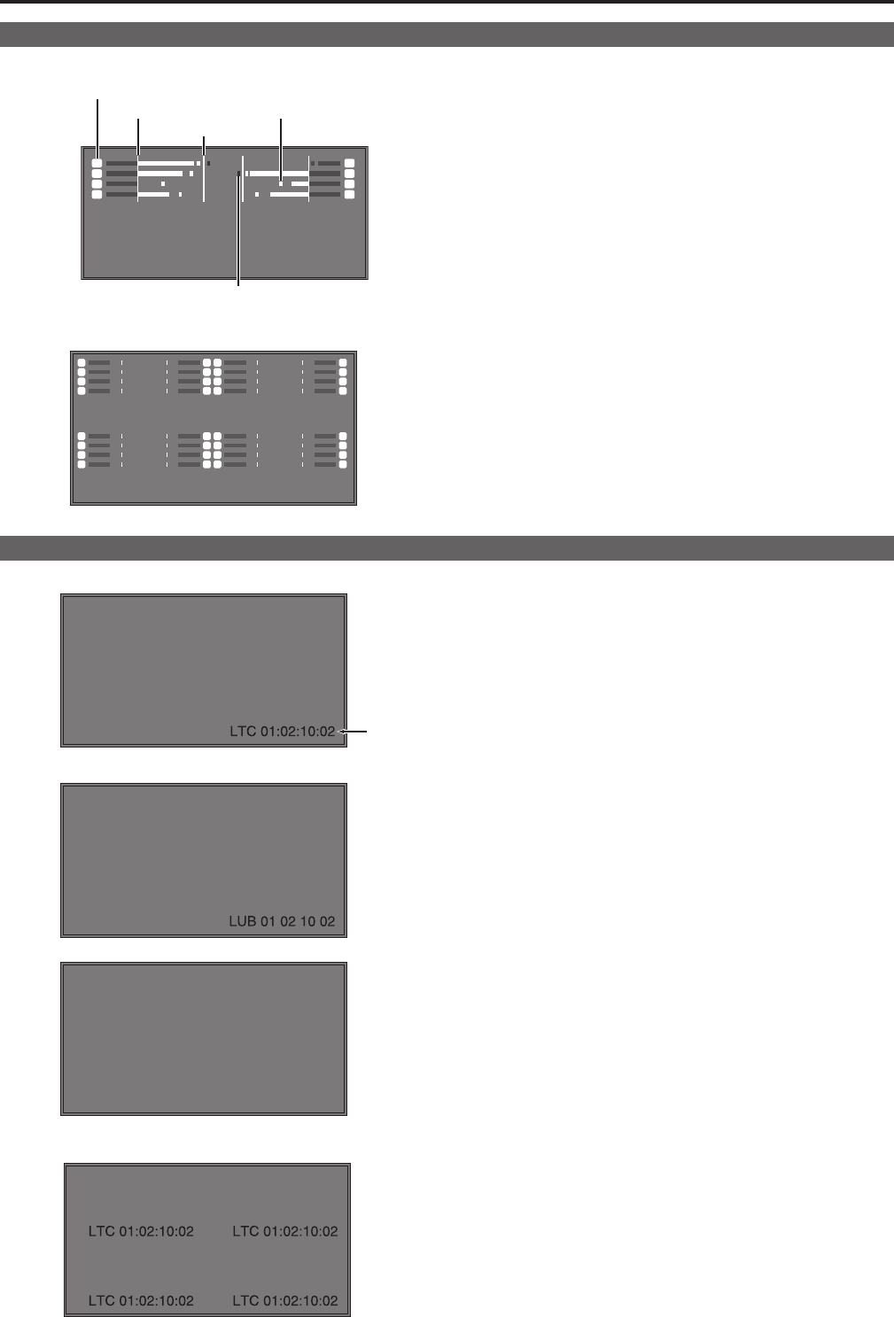
Audio Level Meter Display
● SINGLE screen
11
33
55
77
22
44
66
88
Channel display
Reference point
0 dB point
Peak hold
Overrange
● QUAD screen
11
33
55
77
22
44
66
88
11
33
55
77
22
44
66
88
11
33
55
77
22
44
66
88
11
33
55
77
22
44
66
88
•When SDI, HDMI, and DisplayPort signals are input, a color
bar meter indicates the audio level.
•The display method of the audio level meter can be set in the
menu.(→page47)
•In QUAD screen mode, an audio level meter is displayed for
each of SDI1, SDI2, SDI3, and SDI4.
Display color
Green: Up to reference point (included)
Yellow: Reference point (not included) to 0 dB point (not includ-
ed)
Red: Overrange
Time Code (TC) Display
● SINGLE screen
(:) NDF
(.) DF
LUB
AB
CD
EF
01
LTC 01:02:10:02
● QUAD screen
•The display settings can be set in the menu. Also, the display
mode ([LTC], [VTC], [LUB], [VUB], [LTC+LUB], or [VTC+VUB])
canbeselectedinthemenu.(→page47)
•In QUAD screen mode, the TC is displayed for each of SDI1,
SDI2, SDI3, and SDI4.
<Note>
“VITC” is indicated as “VTC” on this unit.
In LTC and VTC display mode
•Displays the time code in the order of hour : minute : second :
frame.
•In drop-frame mode, a different delimiter is used between the
second and frame indications.
<Note>
Read errors are displayed as “--:--:--:--.”
In LUB and VUB display modes:
•Displays the time code in the order of BG8, BG7, BG6, BG5,
BG4, BG3, BG2, and BG1.
BG: Binary group
•The colon (:) delimiter is not displayed.
<Note>
Read errors are displayed as “-- -- -- --.”
In LTC+LUB and VTC+VUB display modes:
Each combination is displayed separately.


