


ENGLISH - 65
Chapter 4 Settings — [ADVANCED MENU] menu
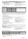
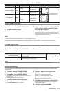
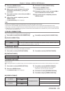
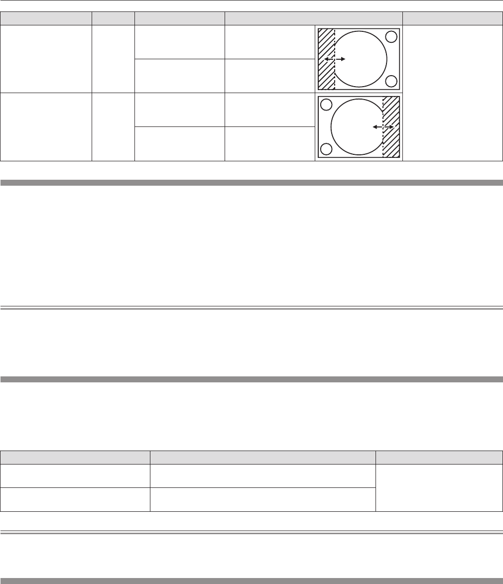
Blanking correction Item Operation Adjustment Range
Left side of the screen [LEFT]
Press
w
.
The blanking zone
moves to the right.
PT-DW740U: 0 to 639
PT-DX810U: 0 to 511
Press
q
.
The blanking zone
moves to the left.
Right side of the
screen
[RIGHT]
Press
w
.
The blanking zone
moves to the right.
Press
q
.
The blanking zone
moves to the left.
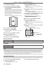
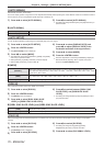
[INPUT RESOLUTION]
You can adjust to achieve an optimal image when there is a ickering image or smeared outlines.
1)
Press as to select [INPUT RESOLUTION].
2)
Press the <ENTER> button.
rf
The [INPUT RESOLUTION] screen is displayed.
3)
Press as to select [TOTAL DOTS], [DISPLAY
DOTS], [TOTAL LINES], or [DISPLAY LINES],
then press qw to adjust it.
rf
Values corresponding to the input signal are displayed
automatically for each item. Change the displayed values and
adjust to the optimal image viewing the screen when there is a
vertical banding or missing in the screen.
Note
rf
Previously mentioned vertical banding will not occur with all white signal input.
rf
The image may be disrupted while performing the adjustment, but it is not a malfunction.
rf
[INPUT RESOLUTION] can be adjusted only when an RGB signal is input to the <RGB 1 IN> terminal or the <RGB 2 IN> terminal.
rf
Certain signals may not be adjustable.
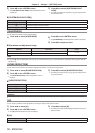
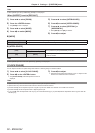
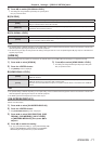
[CLAMP POSITION]
You can adjust the optimal point when the black part of the image is blunt or it has turned green.
1)
Press as to select [CLAMP POSITION].
2)
Press qw to adjust.
rr
Adjustment details
Status Rough guide for optimal value Range
The black part is blunt.
The point where bluntness of the black part improves the most
is the optimal value.
1 - 255
The black part is green.
The point where the green part becomes black, and the
bluntness improves is the optimal value.
Note
rf
[CLAMP POSITION] can be adjusted only when a signal is input to the <RGB 1 IN> terminal or the <RGB 2 IN> terminal.
rf
Certain signals may not be adjustable.
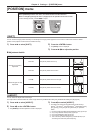
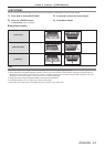
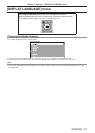
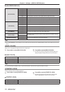
[EDGE BLENDING]
The edge blending function allows multiple projector images to be seamlessly overlapped by using the inclination of the brightness at the
overlapped area.
1)
Press as to select [EDGE BLENDING].
2)
Press qw to switch [EDGE BLENDING].
rf
The setting will change between [ON] and [OFF] each time you
press the button.
rf
To adjust edge blending, proceed to Step 3).
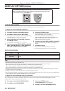
3)
Press the <ENTER> button when [ON] is
selected.
rf
The [EDGE BLENDING] screen is displayed.
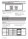
4)
Press as to specify the location to be
corrected.
rf
When joining at top: Set [UPPER] to [ON].
rf
When joining at bottom: Set [LOWER] to [ON].
rf
When joining at left: Set [LEFT] to [ON].
rf
When joining at right: Set [RIGHT] to [ON].
5)
Press qw to switch between [ON] and [OFF].
rf
To adjust edge blending without displaying the adjustment
marker, proceed to Step 8).
6)
Press as to select [MARKER].