


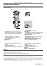
Chapter 2 Getting Started — Connecting
ENGLISH - 27
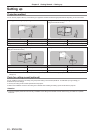
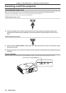
Connecting
Before connecting
f
Before connecting, carefully read the operating instructions for the external device to be connected.
f
Turn off the power of all devices before connecting cables.
f
Take note of the following points before connecting the cables. Failure to do so may result in malfunctions.
g
When connecting a cable to a device connected to the projector or the projector itself, touch any nearby metallic objects to eliminate static
electricity from your body before performing work.
g
Do not use unnecessarily long cables to connect to a device connected to the projector or to the projector body. The longer the cable, the
more it is susceptible to noise. Since using a cable while it is wound makes it act like an antenna, it is more susceptible to noise.
g
When connecting cables, connect GND rst, then insert the connecting terminal of the connecting device in a straight manner.
f
Acquire any connection cable necessary to connect the external device to the system that is either not supplied with the device or not
available as an option.
f
Video signals containing too much jitter may cause the images on the screen to randomly wobble or wafture. In this case, a time base
corrector (TBC) must be connected.
f
The projector accepts video signals, analog RGB signals (synchronous signals are TTL level), and digital signals.
f
Some computer models are not compatible with the projector.
f
Use a cable compensator when you connect devices to the projector using long cables. Otherwise the image may not display properly.
f
Refer to “List of compatible signals” (
x
page 121) for the types of video signals that can be used with the projector.
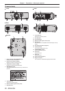
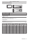
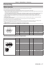
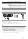
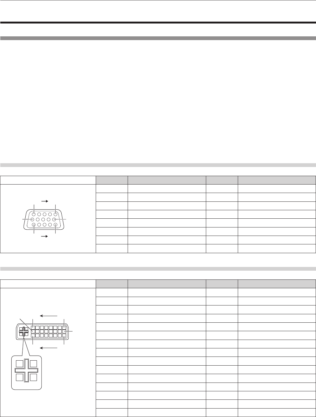
<COMPUTER IN> terminal pin assignments and signal names
Outside view Pin No. Signal name Pin No. Signal name
(10)
(6)
(11) (15)
(1) (5)
(1) R/P
R
(9) ―
(2) G/Y (10) GND
(3) B/P
B
(11) GND
(4) ― (12) DDC data
(5) GND (13) SYNC/HD
(6) GND (14) VD
(7) GND (15) DDC clock
(8) GND
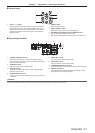
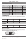
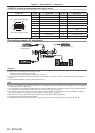
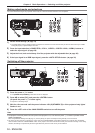
<DVI-I IN> terminal pin assignments and signal names
Outside view Pin No. Signal name Pin No. Signal name
(9)
(17)(24)
(1)(8)
(16)
C4
C1
C3
C2
C5
(1) T.M.D.S data 2
-
(16) Hot plug detection
(2) T.M.D.S data 2+ (17) T.M.D.S data 0
-
(3) T.M.D.S data 2/4 shield (18) T.M.D.S data 0+
(4) ― (19) T.M.D.S data 0/5 shield
(5) ― (20) ―
(6) DDC clock (21) ―
(7) DDC data (22) T.M.D.S clock shield
(8) Analog VD (23) T.M.D.S clock+
(9) T.M.D.S data 1
-
(24) T.M.D.S clock
-
(10) T.M.D.S data 1+ C1 Analog R/P
R
(11) T.M.D.S data 1/3 shield C2 Analog G/G SYNC/Y
(12) ― C3 Analog B/P
B
(13) ― C4 Analog HD/SYNC
(14) +5 V C5 Analog GND
(15) GND