


Input Isolation Transformer Installation
23
Powerware
®
9155 UPS (8–15 kVA) User’s Guide S 164201553 Rev D www.powerware.com
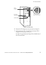
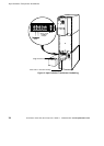
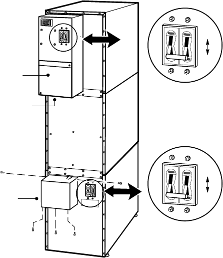
6. Verify that the input circuit breaker is in the OFF position.
7. Remove the UPS wiring access cover and retain.
8. Remove the input isolation transformer wiring cover and retain.
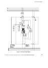
Input Isolation
Transformer
Wiring Cover
Input Circuit Breaker
ON
OFF
ON
OFF
Battery Circuit Breaker
UPS Wiring
Access Cover
Conduit Landing
Figure 8. UPS with Input Isolation Transformer Rear View
9. If you are also installing an optional Maintenance Bypass
Module or Power Distribution Module, proceed to Step 15 on
page 26; otherwise, continue to Step 10.
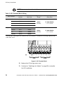
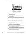
10. On the input isolation transformer, punch the two pilot holes in
the conduit landing for the input and output conduit using a
Greenlee
®
punch or similar device (see Figure 9).
11. Hardwire the input, output, and ground terminations for the
input isolation transformer.
See Table 4 for specifications and Figure 9 for a detailed view of
the input isolation transformer terminal block.