


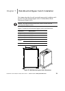
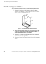

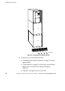
Wall-Mounted Bypass Switch Installation
45
Powerware
®
9155 UPS (8–15 kVA) User’s Guide S 164201553 Rev D www.powerware.com
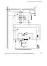
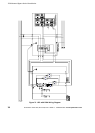
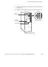
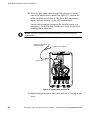
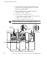
9. Connect the wiring from the bypass switch to the UPS terminal
block.
See Table 9 for specifications and Figure 26 for a detailed view
of the UPS terminal block.
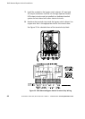
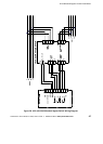
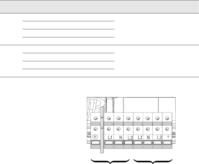
Table 9. UPS Terminal Block Wiring
Wire Function Terminal
Position
Minimum
Wire Size*
Tightening
Torque
Conduit Connection
(Entry Size)
Input
Ground TB1-1 8AWG
p
L1 TB1-3 3AWG
25 lb in 2” access hole for
Neutral
TB1-4 3AWG
2
5
l
b
i
n
(2.83 Nm)
2
a
c
c
e
s
s
h
o
l
e
f
o
r
1-1/2” conduit
L2
TB1-5 3AWG
Output
L1 TB1-6 3AWG
p
Neutral TB1-7 3AWG
25 lb in 2” access hole for
L2
TB1-8 3AWG
2
5
l
b
i
n
(2.83 Nm)
2
a
c
c
e
s
s
h
o
l
e
f
o
r
1-1/2” conduit
Ground
TB1-9 8AWG
*Use o nly 90°C-rated copper wire. Minimum wire size is based on 120/208 full load ratings applied to NEC
Code Table 310-16.
1
2
345678 9
Input Output
TB1
Figure 26. UPS Terminal Block