


51
Powerware
®
9155 UPS (8–15 kVA) User’s Guide S 164201553 Rev D www.powerware.com
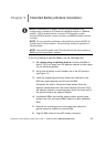
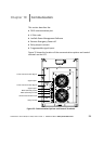
Chapter 9 Extended Battery Module Installation
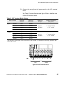
NOTE A maximum of 22 battery strings can be installed in one
configuration, including UPS batteries (4 EBM-64 models or 3 EBM-96
models). UPS-32 models contain 2 strings; UPS-64 models contain
4 strings; EBM -64 models contain 4 strings; and EBM-96 models contain
6strings.
NOTE For non-seismic installations, the stabilizing bracket MUST be
installed on all 3-high cabinets. T he stabilizing bracket is optional for
2-high cabinets.
NOTE In a parallel system, each UPS should have the same number o f
EBMs to ensure equivalent runtimes.
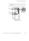
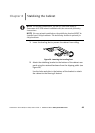
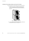
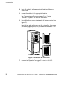
If you are installing an optional EBM(s), use the following steps:
1. For cabinets using a stabilizing bracket: Position the EBM at
least 8” (20.3 cm) away from the adjacent cabinet to allow space
for the stabilizing bracket.
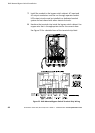
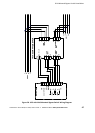
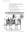
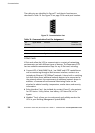
2. Verify that all battery circuit breakers are in the OFF position
(see Figure 31).
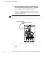
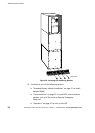
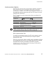
3. Install the supplied ground strap (both ends attached to the
EBM rear panel) between the UPS and the EBM:
Disconnect the end of the ground strap farthest from the
adjacent cabinet and retain the screw. Remove the screw from
the adjacent cabinet’s connecting plate. Attach the loose end of
the ground strap to the adjacent cabinet.
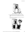
4. If additional EBMs are installed, attach another ground strap
between the first and second EBM. Repeat for each additional
EBM.
5. Reinstall the remaining screw in the open hole where the
ground strap was attached to the last EBM.
6. Plug the EBM cable into the UPS battery connector.