


29
Powerware
®
9155 UPS (8–15 kVA) User’s Guide S 164201553 Rev D www.powerware.com
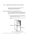
Chapter 6 UPS-Mounted Bypass Switch Installation
This chapter describes the Maintenance Bypass Module and Power
Distribution Module installation. Both modules have a
Make-Before-Break Maintenance Bypass switch.
Maintenance Bypass/Power Distribution Module S etup
If you purchased an optional MBM/PDM, attach the module to the UPS
before any wiring installation. All hardware is supplied in the accessory
kit. Use the following procedure to attach the optional MBM/PDM to the
UPS:
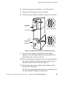
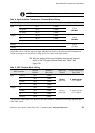
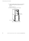
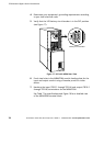
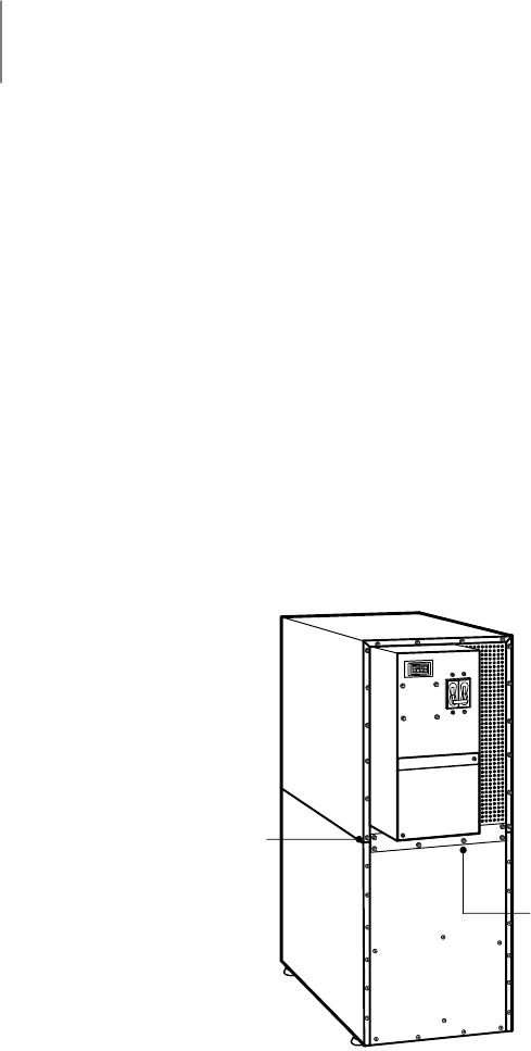
1. Remove the connecting plate between the top cabinet and the
cabinet below it on the UPS rear panel (see Figure 13). Discard
the plate. Retain the screws for later use.
2. Remove the lowest top cover screw on each side of the UPS and
discard.
Connecting Plate
(8 screws)
Lowest Top Cover
Screw (one each side)
Figure 13. UPS Rear View (2-High Cabinet Shown)