


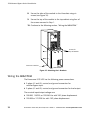
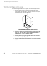
UPS-Mounted Bypass Switch Installation
36
Powerware
®
9155 UPS (8–15 kVA) User’s Guide S 164201553 Rev D www.powerware.com
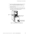
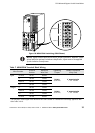
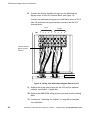
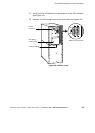
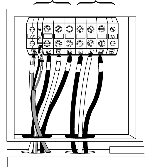
8. Connect the factory-installed wiring from the Maintenance
Bypass switch to the UPS terminal block (see Figure 19).
Connect the maintenance bypass (red and black) wires to TB1-2
(the A/B maintenance bypass auxiliary contacts) on the UPS
terminal block.
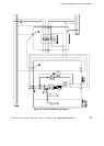
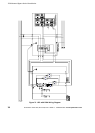
123 4 5 6 7 8 9
A/B Maintenance
Bypass Auxiliary
Contacts
TB1
Input
Output
Figure 19. Wiring from Maintenance Bypass Switch to UPS
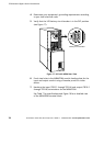
9. Replace the wiring access cover on the UPS and the optional
isolation transformer, if applicable.
10. Replace the MBM/PDM wiring access cover and conduit landing
plate.
11. Continue to “Stabilizing the Cabinet” on page 49 to complete
the installation.