


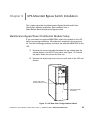
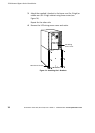
UPS-Mounted Bypass Switch Installation
35
Powerware
®
9155 UPS (8–15 kVA) User’s Guide S 164201553 Rev D www.powerware.com
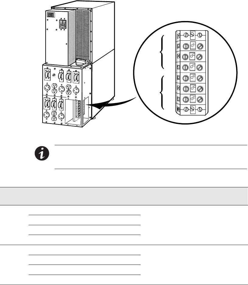
TB10
8
7
6
5
4
3
2
1
Input
Output
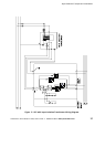
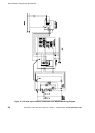
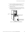
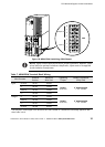
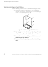
Figure 18. MBM/PDM Hardwiring (PDM Shown)
NOTE Input neutral must be wired for proper operation. However, when
wired with the optional isolation transformer, input neutral is supplied
by the isolation transformer.
Table 7. MBM/PDM Terminal Block Wiring
Wire Function
Terminal
Position
Minimum
Wire Size*
Tightening
Torque
Conduit Connection
(Entry Size)
Input
Ground TB10-1 8AWG
p
L1 TB10-2 3AWG
25 lb in 2” access hole for
Neutral
TB10-3 3AWG
2
5
l
b
i
n
(2.83 Nm)
2
a
c
c
e
s
s
h
o
l
e
f
o
r
1-1/2” conduit
L2
TB10-4 3AWG
Output
L1 TB10-5 3AWG
p
Neutral TB10-6 3AWG
25 lb in 2” access hole for
L2
TB10-7 3AWG
2
5
l
b
i
n
(2.83 Nm)
2
a
c
c
e
s
s
h
o
l
e
f
o
r
1-1/2” conduit
Ground
TB10-8 8AWG
*Use o nly 90°C-rated copper wire. Minimum wire size is based on 120/208 full load ratings applied to NEC
Code Table 310-16.