


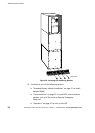
Wall-Mounted Bypass Switch Installation
46
Powerware
®
9155 UPS (8–15 kVA) User’s Guide S 164201553 Rev D www.powerware.com
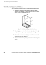
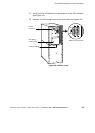
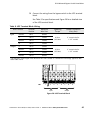
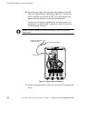
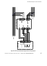
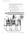
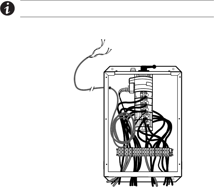
10. Route the gray signal cable through the grommet on the left
side of the bypass switch cabinet (see Figure 27). Connect the
white and black pair of wires to TB1-2 (the A/B maintenance
bypass auxiliary contacts) on the UPS terminal block.
Secure each connection, tightening the terminal screws to a
maximum 3.5 in lb (0.4 Nm). Provide strain relief for cables by
installing plastic cable ties.
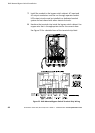
NOTE DO NOT connect the red and black pair of wires in the gray
signal cable.
Signal Cable
To UPS Terminal Block
Do Not Connect Red
and Black Wires
Figure 27. Signal Cable Installation
11. Replace the bypass switch front cover and the UPS wiring access
cover.