


Extended Battery Module Installation
52
Powerware
®
9155 UPS (8–15 kVA) User’s Guide S 164201553 Rev D www.powerware.com
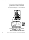
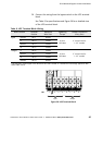
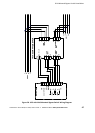
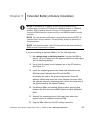
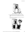
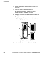
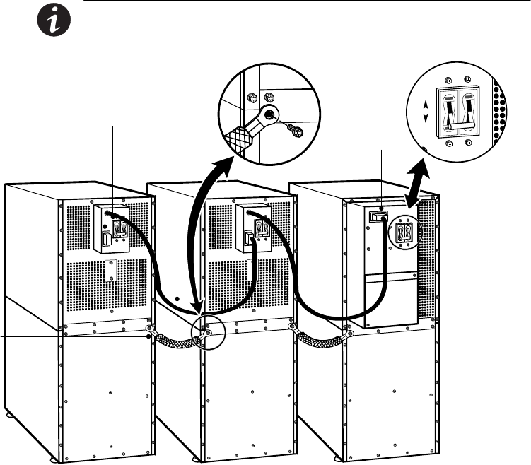
7. If additional EBMs are installed, plug the EBM cable of the
second cabinet into the battery connector on the first EBM.
Repeat for each additional EBM.
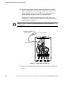
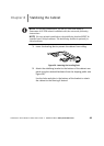
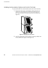
8. Attach a stabilizing bracket to each EBM if needed (see
“Stabilizing the Cabinet” on page 49).
9. Continue to one of the following sections:
Ī “Communication” on page 53 to install UPS communication
options, such as X-Slot cards or REPO.
Ī “Operation” on page 65 to start up the UPS.
NOTE After UPS startup, ensure maximum battery runtime by
configuring the UPS for the correct number o f EBMs (see page 75).
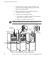
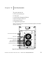
UPS Battery
Connector
Ground
Strap
EBM Battery
Circuit Breaker
EBM Battery Connector
EBM Cable
ON
OFF
UPS Battery
Circuit Breaker
Figure 31. Typical EBM Installation (2-High Cabinets Shown)