


Communication
61
Powerware
®
9155 UPS (8–15 kVA) User’s Guide S 164201553 Rev D www.powerware.com
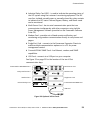
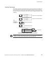
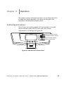
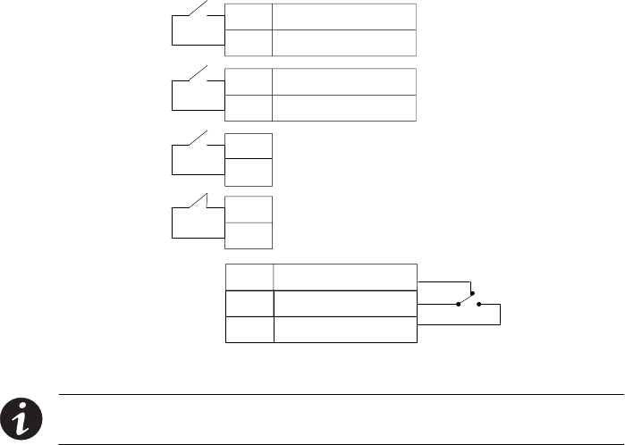
Control Terminals
The cables should be connected to the control terminals with cable clips.
Input and output terminals have a functional isolation from terminal to
terminal. They are connected to the UPS chassis through individual 1 MΩ
resistors.
+Polarity
–Polarity
2
1
+Polarity
–Polarity
2
1
2
1
2
1
Signal Input 1 (Programmable)
Signal Input 2 (Programmable)
REPO Normally Open
REPO Normally Closed
Normally Open
Normally Closed
1
2
Common
3
Relay Output
UPS
Connectors
(see Figure 32
on page 53)
Figure 39. External Control Terminal Connections
NOTE If using a semiconductor switch type, pay attention to the proper
polarity. A relay or other mechanical control is preferred.