


53
Powerware
®
9155 UPS (8–15 kVA) User’s Guide S 164201553 Rev D www.powerware.com
Chapter 10 Communication
This section describes the:
Ī DB -9 communication port
Ī X-Slot cards
Ī LanSafe Power Management Software
Ī Remote Emergency Power-off
Ī Relay output contacts
Ī Programmable signal inputs
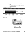
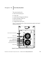
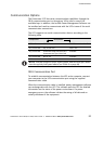
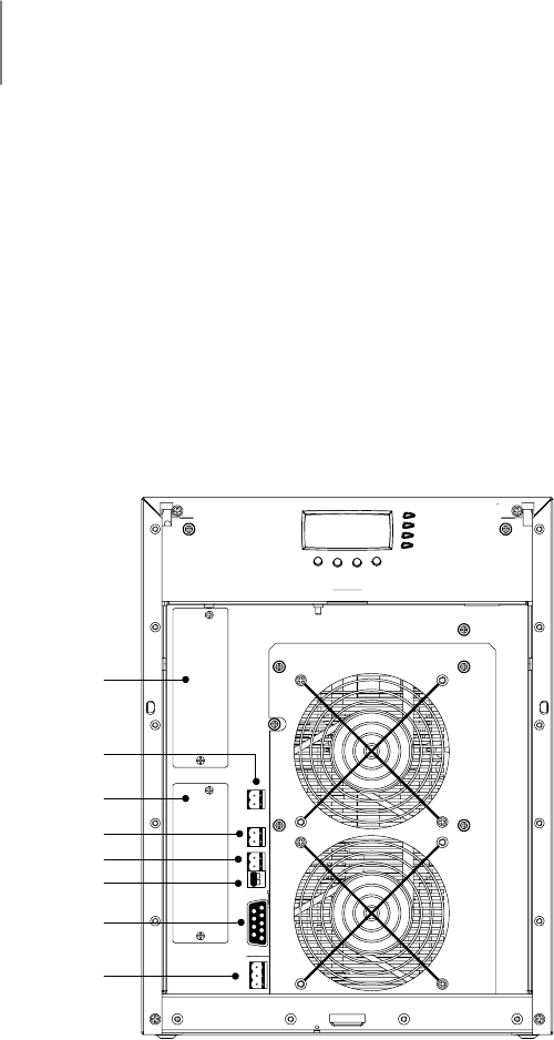
Figure 32 shows the location of the communication options and control
terminals on the UPS.
DB-9 Communication Port
REPO (Normally Closed)
REPO (Normally Open)
Signal Input 2
Signal Input 1
X-Slot Communication Bay #2
X-Slot Communication Bay #1
Relay Contact
Figure 32. Communication Options and Control Terminals