


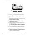
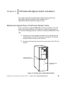
UPS-Mounted Bypass Switch Installation
33
Powerware
®
9155 UPS (8–15 kVA) User’s Guide S 164201553 Rev D www.powerware.com
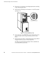
Output overcurrent protection and disconnect switch must be provided
by others.
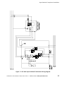
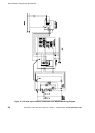
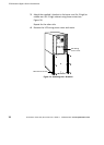
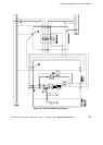
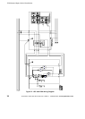
Figure 20 and Figure 21 beginning on page 37 show the oneline diagrams
of the MBM and PDM with the UPS.
WARNING
Only qualified service personnel (such as a licensed electrician) should perform
the UPS installation and initial startup. Risk of electrical shock.
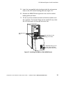
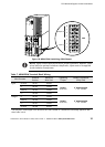
Use the following procedure to hardwire the MBM/PDM:
1. Verify that the electrical connections to the installation site have
been properly installed.
2. A wall -mounted, user-supplied, readily-accessible disconnection
device must be incorporated in the input wiring.
Compare the circuit breaker ratings and wire sizes to the ones in
the following wiring table:
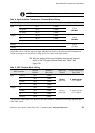
Table 6. Circuit Breaker Ratings
UPS Capacity Input Circuit Breaker Rating Minimum Wire Size*
8kVA 60A 4AWG(21.2mm
2
)
10 kVA 80A 3AWG(26.7mm
2
)
12 kVA 100A 2AWG(33.6mm
2
)
15 kVA 100A 2AWG(33.6mm
2
)
*Use only 90°C-rated copper wire. Minimum wire size is based on 120/208 full load
ratings applied to NEC Code Table 310-16. Code may require a larger AWG size than
shown in this table because of temperature, number of conductors in the conduit,
or long service runs. Follow local requirements.
NOTE To accommodate the feature of easy system expandability, it is
recommended that initial installation of the Powerware 9155 UPS contain
wiring to support the maximum capacity of the UPS cabinet.
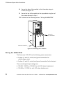
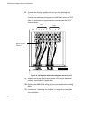
3. Switch off utility power to the distribution point where the UPS
will be connected. Be absolutely sure there is no power.