


Communication
63
Powerware
®
9155 UPS (8–15 kVA) User’s Guide S 164201553 Rev D www.powerware.com
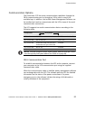
Relay Contacts
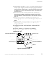
The UPS incorporates a programmable relay output with potential free
contactsforremotealarmindications(seeFigure32onpage53).An
additional four relay outputs can be obtained with the X-Slot compatible
Relay Interface Card.
WARNING
The relay contacts must not be connected to any utility connected circuits.
Reinforced insulation to the utility is required. The relay contacts must have a
maximum rating of 30 Vdc/1A and 60 Vdc/2A nominal values.
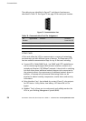
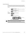
Programmable Signal Inputs
The UPS incorporates two programmable signal inputs (see Figure 32 on
page 53). Use of non-polar (relay) control input is recommended. The
pins must be shorted with maximum resistance of 10 ohm in order to
activate the specific input.
NOTE SeeFigure39onpage61forthepolarityandverifythese
connections if polarity control i s required.
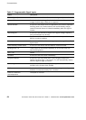
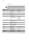
The default and programmable settings for the signal inputs are shown in
Table 11.