Rev.2.00 Nov 28, 2005 page 179 of 378
REJ09B0124-0200
M16C/6N Group (M16C/6NK, M16C/6NM) 15. Serial Interface
Under development
This document is under development and its contents are subject to change.
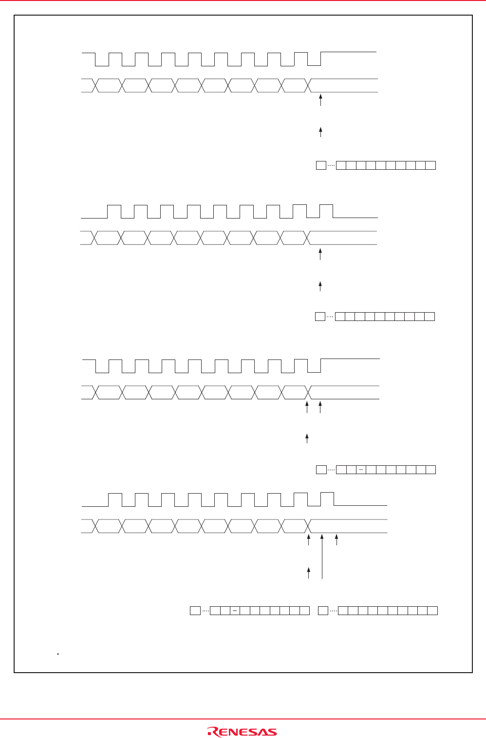
Figure 15.24 Transfer to UiRB Register and Interrupt Timing
i = 0 to 2
This diagram applies to the case where the following condition is met.
The CKDIR bit in the UiMR register = 0 (slave selected)
(1) IICM2 = 0 (ACK and NACK interrupts), CKPH = 0 (no clock delay)
ACK interrupt (DMA1 request),
NACK interrupt
Transfer to UiRB register
D6 D5 D4 D3 D2 D1 D8 (ACK, NACK)
D8 (ACK, NACK)
D8 (ACK, NACK)
D7
SDAi
SCLi
D0
1st bit 2nd bit 3rd bit 4th bit 5th bit 6th bit 7th bit 8th bit 9th bit
b15 b9 b8 b7 b0
D
8 D7 D6 D5 D4 D3 D2 D1 D0
UiRB register
D6 D5 D4 D3 D2 D1
D7
SDAi
SCLi
D0
b15 b9 b8 b7 b0
1st bit 2nd bit 3rd bit 4th bit 5th bit 6th bit 7th bit 8th bit 9th bit
(2) IICM2 = 0, CKPH = 1 (clock delay)
ACK interrupt (DMA1 request),
NACK interrupt
Transfer to UiRB register
UiRB register
(3) IICM2 = 1 (UART transmit/receive interrupt), CKPH = 0
Receive interrupt
(DMA1 request)
Transmit interrupt
Transfer to UiRB register
D6 D5 D4 D3 D2 D1
D7
SDAi
SCLi
D0
b15 b9 b8 b7 b0
1st bit 2nd bit 3rd bit 4th bit 5th bit 6th bit 7th bit 8th bit 9th bit
UiRB register
(4) IICM2 = 1, CKPH = 1
D6 D5 D4 D3 D2 D1
D7
SDAi
SCLi
D0
D8 (ACK, NACK)
b15 b9 b8 b7 b0 b15 b9 b8 b7 b0
1st bit 2nd bit 3rd bit 4th bit 5th bit 6th bit 7th bit 8th bit 9th bit
Transmit interrupt
Transfer to UiRB register
Receive interrupt
(DMA1 request)
Transfer to UiRB register
UiRB register
UiRB register
D8 D7 D6 D5 D4 D3 D2 D1 D0
D7 D6 D5 D4 D3 D2 D1D0
D8 D7 D6 D5 D4 D3 D2 D1 D0D7 D6 D5 D4 D3 D2 D1D0


