Rev.2.00 Nov 28, 2005 page 291 of 378
REJ09B0124-0200
M16C/6N Group (M16C/6NK, M16C/6NM) 21. Flash Memory Version
Under development
This document is under development and its contents are subject to change.
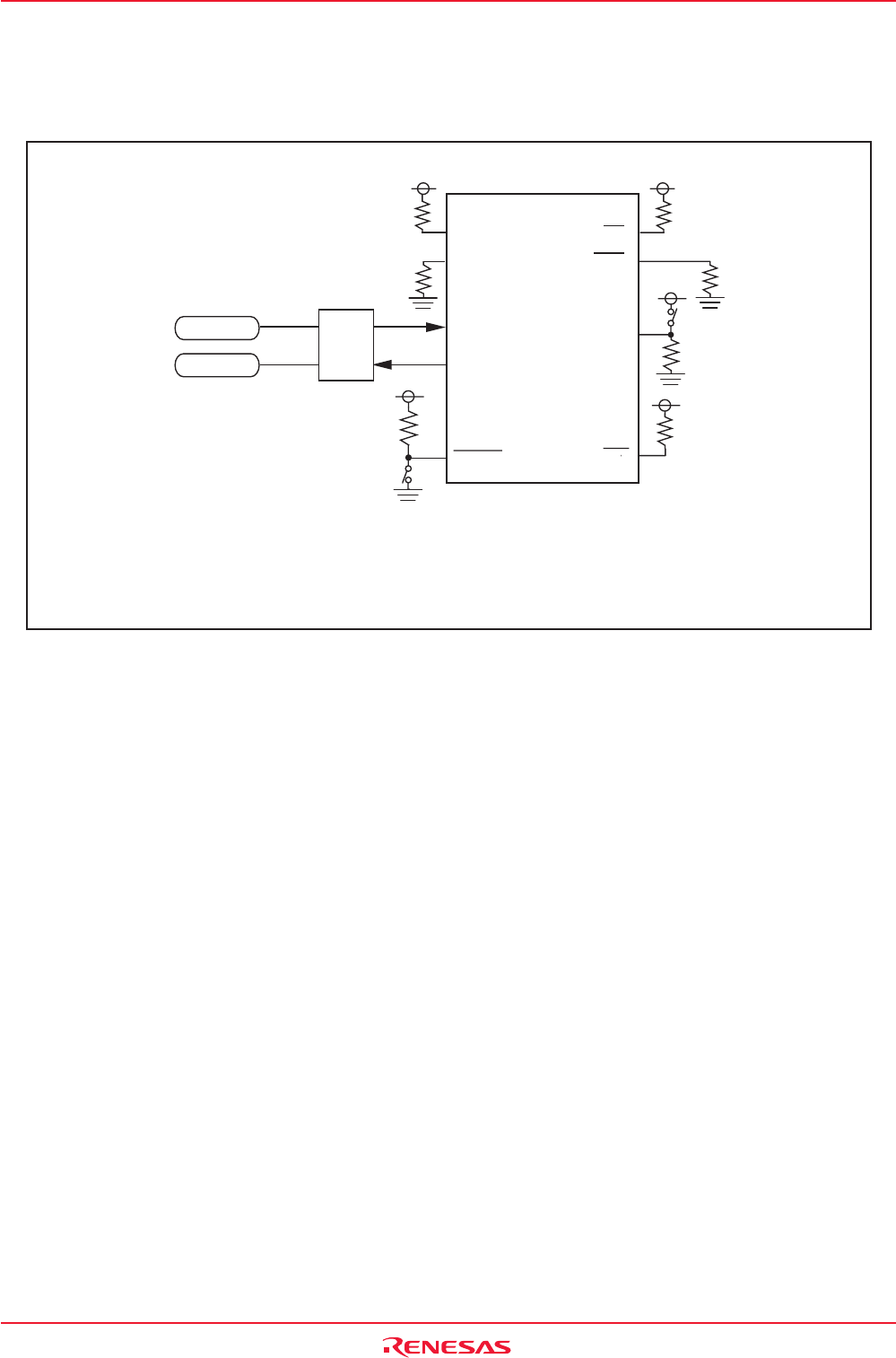
21.6.2 Example of Circuit Application in CAN I/O Mode
Figure 21.19 shows example of circuit application in CAN I/O mode. Refer to the user’s manual of your
CAN programmer to handle pins controlled by a CAN programmer.
CNVSS
Microcomputer
CAN_L
CAN_H
CAN_L
CAN_H
CAN transceiver
P6_7/TXD1
P9_6/CTX0
P9_5/CRX0
P6_5/CLK1
RESET
P8_5/NMI
P5_0(CE)
P5_5(EPM)
NOTES:
1.Control pins and external circuitry will vary according to programmer.
For more information, refer to the programmer manual.
2.In this example, modes are switched between single-chip mode and CAN I/O mode
by controlling the CNVSS input with a switch.
VCC1
VCC1
VCC1
VCC2
VCC1
Figure 21.19 Circuit Application in CAN I/O Mode


