


ULTRAMATRIX E-SERIES MANUAL
8
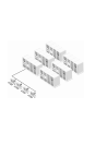
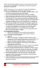
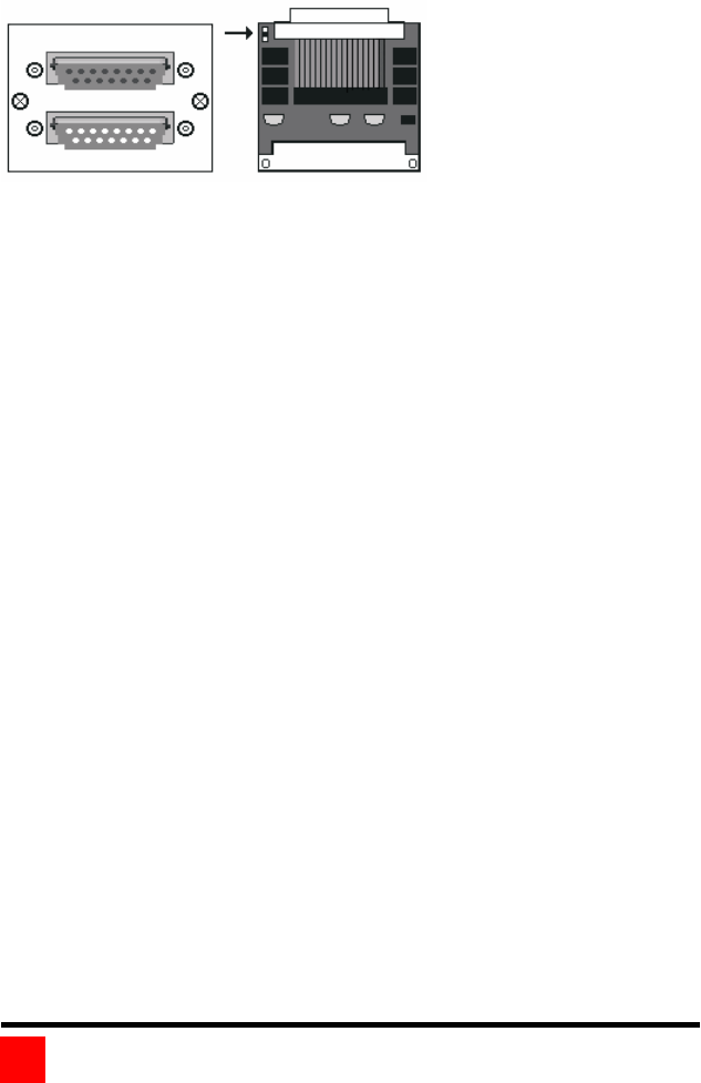
The 4xE model can have two expansion cards installed. The bottom
expansion card transmits the signals for KVM 1 and 2; the top
expansion card transmits the signals for KVM 3 and 4. If an expansion
card is permanently removed, a terminator and cover plate must be
installed.
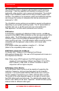
Two expansion cards are
installed in the 4xE model
Figure 2. Expansion card
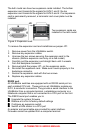
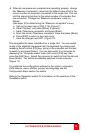
To remove the expansion card and install/remove jumper JP1:
1. Remove power from the UltraMatrix switch.
2. Remove any expansion cables.
3. Unscrew the two screws securing the expansion card to the
chassis. (Bottom expansion card only on a 4xE model)
4. Carefully pull the expansion card straight back until it unseats
from the backplane connector.
5. Remove/install the jumper JP1, on the expansion cards.
6. Re-install the expansion card. Make sure it seats properly in the
backplane connector.
7. Secure the expansion card with the two screws.
8. Replace any expansion cables
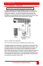
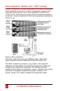
RS232 port
All UltraMatrix switches are equipped with an RS232 serial port on
each installed CPU slot. These ports on all UltraMatrix models are
RJ12, 6-conductor connectors. They provide a serial interface to the
UltraMatrix from a computer terminal, a standalone computer or a
Notebook computer that is not connected to a CPU port on the Unit.
The RS232 serial port enables you to:
Upgrade the system firmware
Restore a Unit to its factory default settings
Configure an expansion switch
Switch a KVM station to a CPU port
An adapter and serial cable are provided for serial interface.
Firmware cannot be updated from a computer terminal.
IN
OUT
JP1