


ULTRAMATRIX E-SERIES MANUAL
22
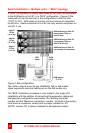
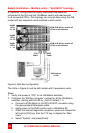
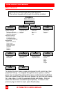
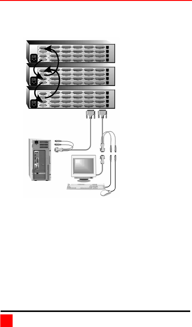
Switch Installation – Multiple units – “Split-BUS” topology
A “Split Bus” configuration is usually used when the users are
connected to the first and last UltraMatrix switch and need access
to all connected CPUs. This topology can only be done using the 4xE
model with two expansion cards installed in each switch.
Figure 6. Split-Bus configuration
The Units in Figure 6 must be 4xE models with 2 expansion cards.
Steps:
1. Verify that power is “OFF” on all UltraMatrix switches.
2. Configure the “Starting computer” number for all the UltraMatrix
switches, starting with Unit #2 by: (Unit #1 default = 1)
a. Connect a KVM station to Unit #2’s KVM #1 connector using
the appropriate KVM adapter cable.
b. Apply power to the KVM monitor and to UltraMatrix #2.
c. When the internal diagnostic completes, press and release the
left control [Ctrl] key, then the F12 key to display the “Main
menu”.
d. Select “System” and press [Enter].
KVM #3 & #4 can access all
CPUs on all switches.
KVM #1 & #2 can access all
CPUs on all switches
Unit#3
CPUs
33 - 48
Unit#2
CPUs
16 - 32
Unit#1
CPUs
1
-
16
KVM station
(1 of 4)
CPU
Cable
KVM
Cable