


ULTRAMATRIX E-SERIES MANUAL
42
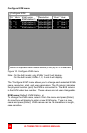
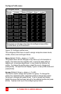
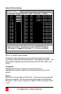
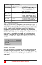
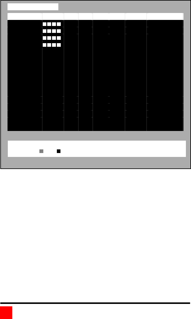
System Status display
System Status
Computers Power Pos
Ver KVM
CPU
User Status
1-4
1
21C
PC
1
User 1
Share mode
5-8
2
21C
PC
2
User 2
Share mode
9-12
3
21C
PC
3
User 3
Share mode
13-16
4
21C
PC
4
User 4
Share mode
17-20 1
21C
PC
No response
21-24 2
21C
PC
No response
25-28 3
21C
PC
No response
29-32 4
21C
PC
No response
33-36 1
21C
PC
No response
37-40 2
21C
PC
No response
41-44 3
21C
PC
No response
45-48 4
21C
PC
No response
49-52 1
21C
PC
No response
53-56 2
21C
PC
No response
57-60 3
21C
PC
No response
61-64 4
21C
PC
No response
Figure 14. System status display
The system status display is a very powerful and useful tool when
monitoring, expanding, troubleshooting, or reconfiguring a system. The
status screen displays reported information from all CPU cards in the
system.
Computers
Indicates the CPU port numbers for a given CPU card.
Highlighted computer numbers are the total computer ports in the
system.
Power
Each CPU card represents 4 CPU ports. These ports are represented
by the four squares. The CPU ports are (Left square to right square),
CPU port 1, port 2, port 3, and port 4. (Green = CPU is on, Red = CPU
is off)
Pos=Card position
| Ver=Program version | KVM=PC/Sun/None
CPU power
=on
=off | Line color
Good
Disconnected
Error