


ULTRAMATRIX E-SERIES MANUAL
19
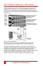
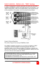
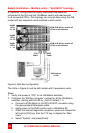
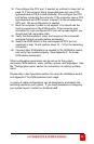
Switch Installation – Multiple units – “RING” topology
A “RING” configuration is usually used when the users are connected
to different UltraMatrix switches and need access to all computers. In a
“RING” configuration, users on any KVM station in the ring can access
all the computers in the system on a first-come-first-serve basis.
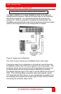
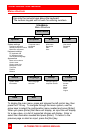
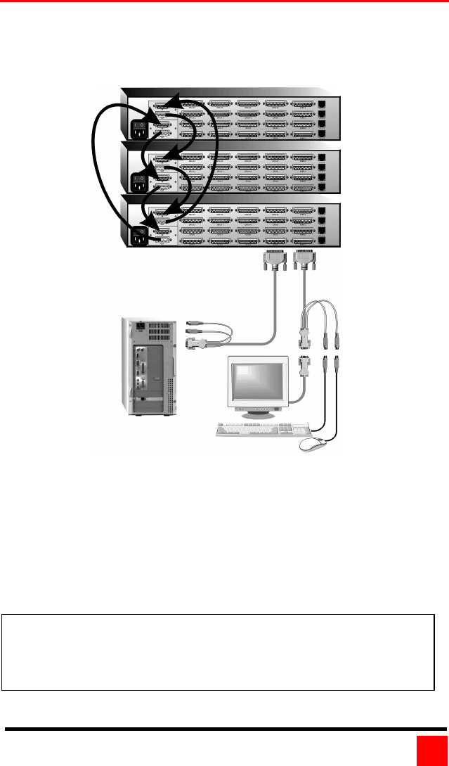
Figure 5. Ring configuration
The Units in Figure 5 can be any UltraMatrix model
The “RING” installation procedure is very similar to installing a “BUS”
configuration with the exception of removing jumper JP1 on the
expansion cards on two Units and adding an expansion cable(s) from
the first Unit to the last Unit. This additional expansion cable(s) from the
first Unit to the last Unit creates the “RING”.
All Units must be equipped with an expansion card(s).
A KVM station on
Unit #3 can access
all computers.
A KVM station on
Unit #2 can access
all computers.
A KVM station on
Unit #1 can access
all computers.
JP1
off
JP1
on
JP1
off
Unit #3
CPUs
33 - 48
Unit #2
CPUs
16 – 32
Unit #1
CPUs
1
–
16
KVM station
(1 of 4)
CPU
Cable
KVM
Cable
In the example used in Figure 5, removing jumper JP1 on Unit #1
and #3 divides the total ring cable length approximately in half.
Unit #3 (IN) to Unit #1 (OUT) = 20’
Unit #3(OUT) to Unit #2 (IN), Unit #2 (OUT) to Unit #1 (IN) = 20’.