


Cables and Pinouts
B-4
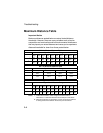
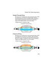
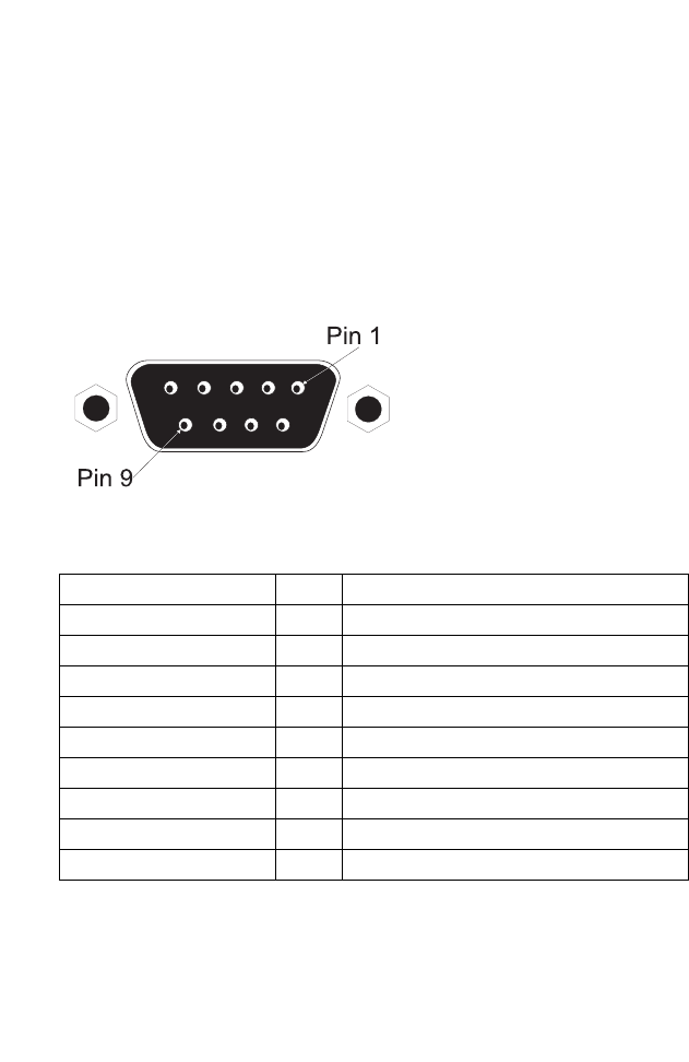
Console Port Pin Assignments
The DB-9 DCE serial port on the front panel of the
SMC2555W-AG is used to connect to the access point for
out-of-band console configuration. The on-board menu-driven
configuration program can be accessed from a terminal, or a PC
running a terminal emulation program. The pin assignments used
to connect to the serial port are provided in the following tables.
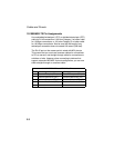
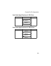
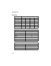
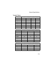
Wiring Map for Serial Cable
Signal (serial port) Pin Signal (management console port)
Unused 1 Unused
TXD (transmit data) 2 RXD (receive data)
RXD (receive data) 3 TXD (transmit data)
Unused 4 Unused
GND (ground) 5 GND (ground)
Unused 6 Unused
CTS (clear to send) 7 RTS (request to send)
RTS (request to send) 8 CTS (clear to send)
Unused 9 Unused
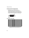
Note: The left hand column pin assignments are for the female DB-9 connector on the access
point. Pin 2 (TXD or “transmit data”) must emerge on the management console’s end of
the connection as RXD (“receive data”). Pin 7 (CTS or “clear to send”) must emerge on
the management console’s end of the connection as RTS (“request to send”).