


Introduction
1-4
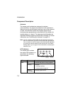
Component Description
Antennas
The access point includes two antennas for wireless
communications. The signal transmitted from both antennas is
identical, but only the best signal received on one of the antennas
is used. The antennas transmit the outgoing signal along a
horizontal plane perpendicular to the antenna (in the shape of a
toroidal sphere, or a donut). The antennas should therefore be
adjusted to different angles to provide better coverage. For further
information, see “Positioning the Antennas” on page 2-3.
Note: You can install an optional SMC 2.4 GHz high-gain antenna for
802.11b and/or 802.11g clients in the socket on the right antenna.
Also, remember to order the jumper cable (SMC2555W-JMPRCBL)
to connect an external antenna to the access point. See “Radio
Settings (802.11g)” on page 5-44 for information on selecting the
antenna in use.
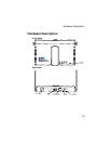
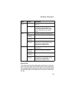
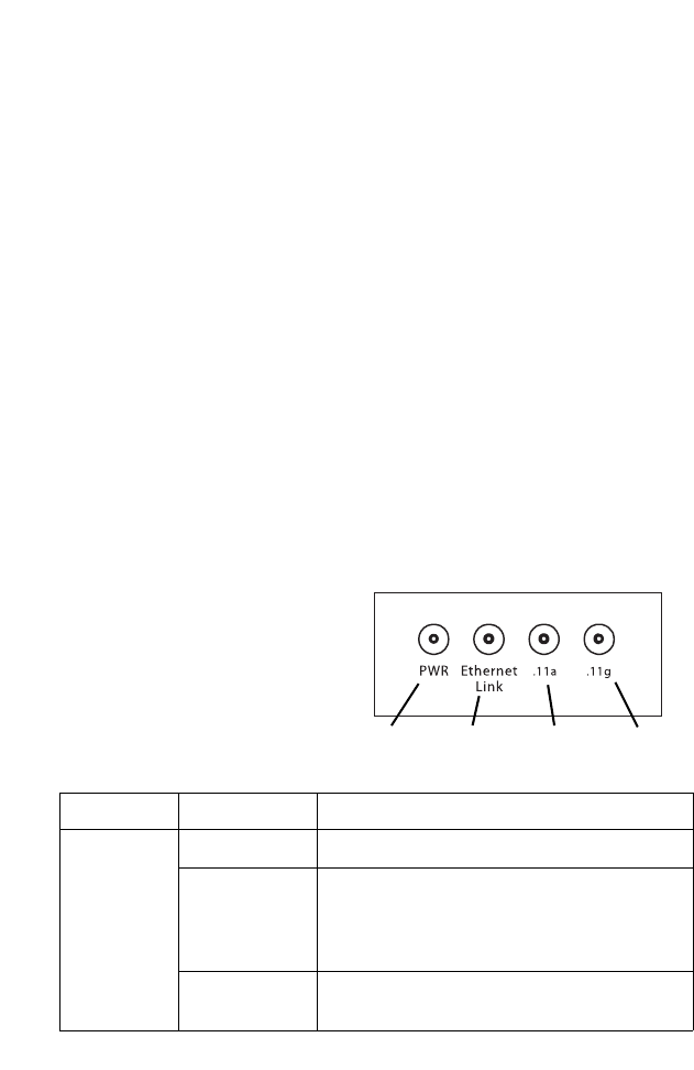
LED Indicators
The access point includes
four status LED indicators, as
described in the following
figure and table.
LED Status Description
PWR On Indicates that power is being supplied.
Flashing Indicates -
• running a self-test
• loading software program
Flashing
(Prolonged)
Indicates system errors
Power
802.11a
Wireless
Link/Activity
Ethernet
Link/Activity
802.11b/g
Wireless
Link/Activity