


Preparation
Connections
10
Connections
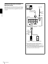
To enable printing, video equipment to act as an input
signal source, and a video monitor to display images or
menus must be connected.
The following diagrams illustrate how to make the input,
output and remote control connections. Use this as a
guide when connecting the cables required to transmit
signals to and from the equipment to be used for
printing.
Notes
• Turn off the power of each device before attempting to
make any connections.
• Connect the AC power cord last.
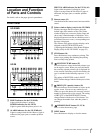
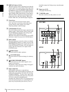
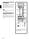
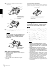
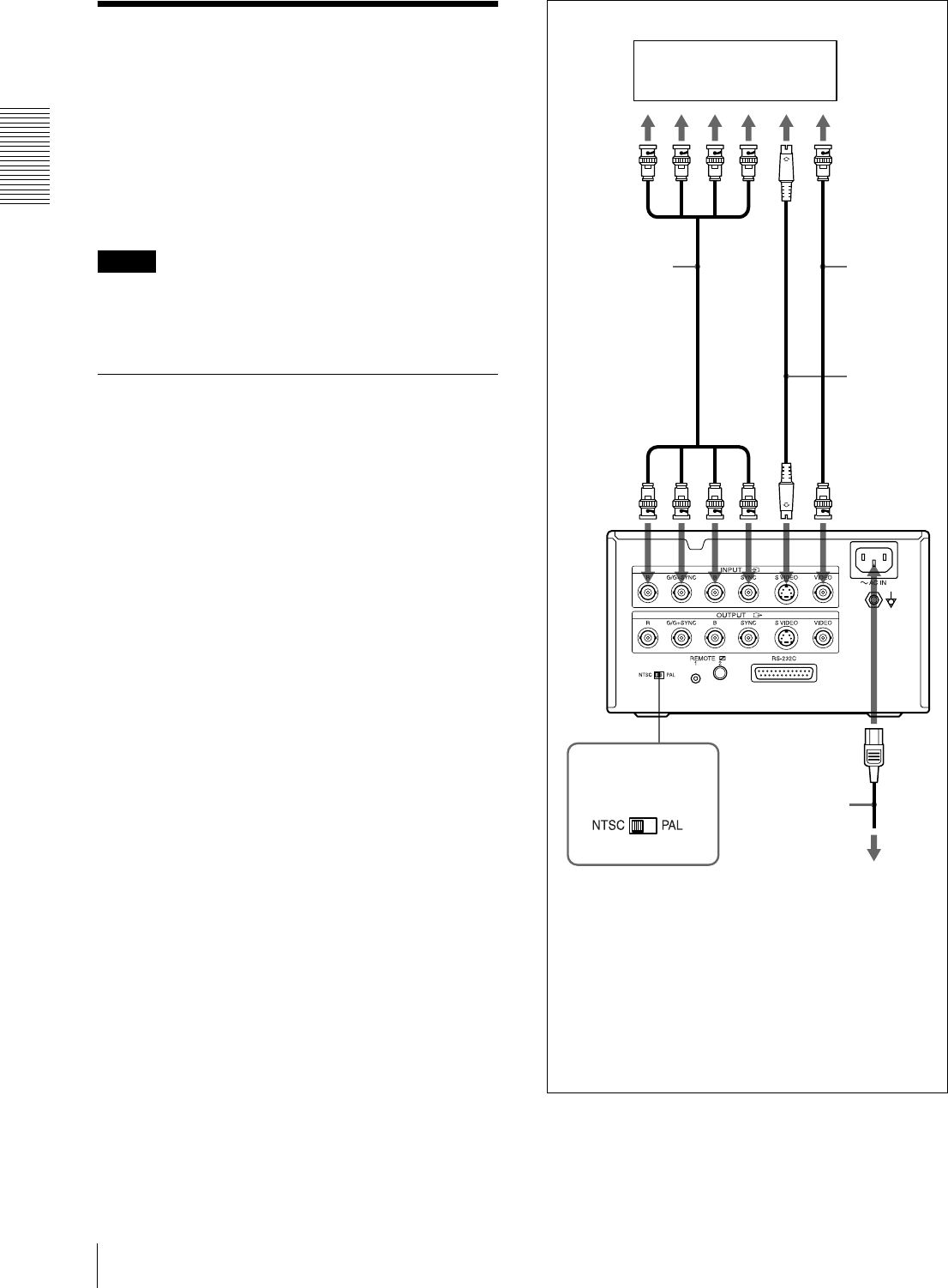
Connecting Video Equipment
Connect the video equipment providing the video
images to be printed.
Connect the video equipment which will be used in
actual printing, using the following diagram as a guide.
Before connecting the video equipment, see “Important
safeguards/notices for use in the medical environments”
on page 2.
Video equipment
to RGB
output
connectors
to composite
video output
connector
to S VIDEO
output
connector
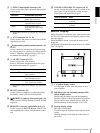
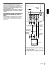
75-ohm
coaxial cable
with BNC
connectors
75-ohm
coaxial cable
with BNC
connectors
Connecting
cable (with
DIN 4-pin
connectors)
to RGB SYNC
b)
INPUT
to S
VIDEO
INPUT
to VIDEO
INPUT
to AC IN
AC power cord
(supplied)
to wall outlet
NTSC/PAL selector
a)
a) Set the NTSC/PAL selector to match your TV system. To
switch the TV system, turn the power off once, then change
the setting. If you change the setting with the power on, this
mode will not be switched.
b) Only for the UP-21MD.
UP-21MD