


Chapter 11 Replacing a Server or Replacing Individual Components 11-15
11.6.2 Installing the New System Board
Note – The system board contains a jumper (JP8) that identifies the hardware to the
system software as either a Sun Fire V120 or a Netra 120. The factory default setting
for JP8 on FRU replacement system boards (F375-3064 and F275-3065) identifies
them as Sun Fire V120s. Before installing a new system board, make sure that the
setting for JP8 is correct for the model of system you are installing it into. To check
the jumper settings, see Appendix D. Do not alter any other jumper settings.
1. Check that the setting for jumper JP8 on the new system board is correct for the
model of server you are installing it into (see Appendix D).
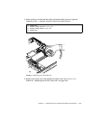
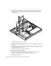
2. Insert the new system board at an angle, and locate it so that the SCSI, Ethernet,
and serial connectors are firmly positioned in their slots at the rear of the chassis.
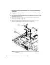
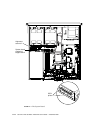
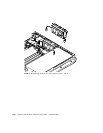
3. Now position the system board on the alignment stand-off between the PSU fan
and hard disk drive bay 1 (see
FIGURE 11-7).
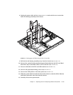
4. Insert the SCSI pillars (see
FIGURE 11-7) and replace their screws loosely.
5. Insert all system board fixing screws loosely (see
FIGURE 11-7). Do not put any
screws in the holes for the PCI card slide retainer.
6. Tighten up the SCSI pillars, then tighten all the other screws.
7. Replace the PCI card slide retainer.
8. Replace the DIMMs that you removed from the old system board (see Section 4.5,
“Installing and Removing Memory” on page 4-9).
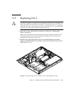
9. Replace the rear fan assembly (see Section 11.8, “Replacing the Rear Fan
Subassembly (Fans 1 and 2)” on page 11-19).