3-6 Sun Fire V120 and Netra 120 Server User’s Guide • December 2001
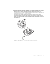
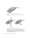
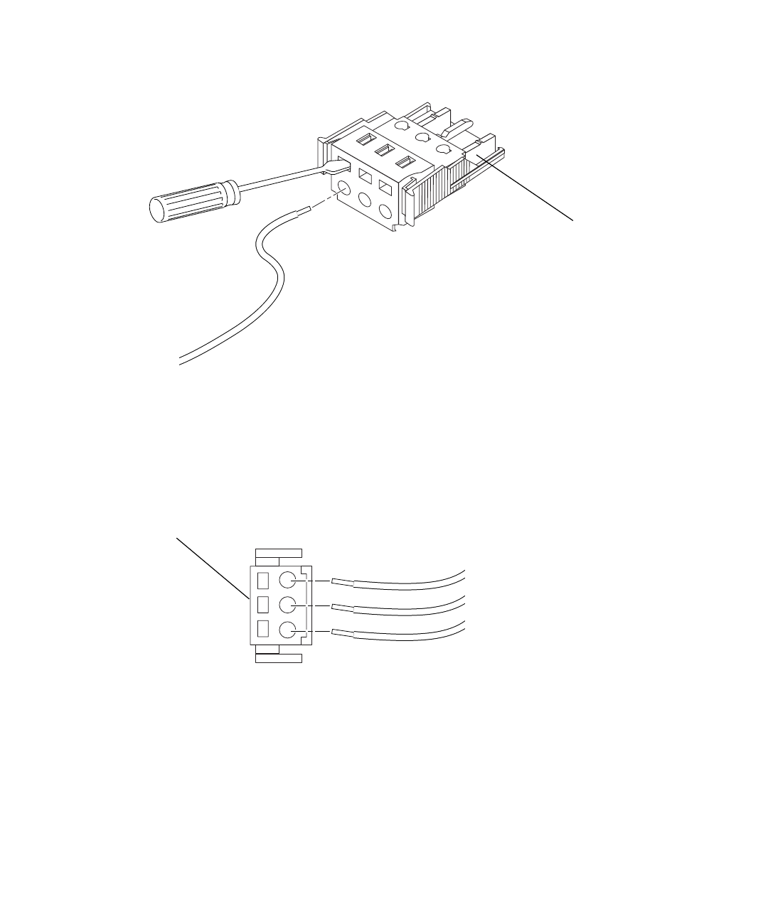
FIGURE 3-4 Opening the DC Connector Cage Clamp (Screwdriver Method)
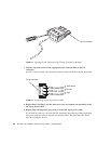
7. Feed the exposed section of the appropriate wire into that hole in the DC
connector.
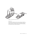
FIGURE 3-5 shows which wires should be inserted into each hole in the DC connector.
FIGURE 3-5 Assembling the DC Input Power Cable
8. Repeat Step 6 and Step 7 for the other two wires to complete the assembly of the
DC input power cable.
9. Repeat Step 4 through Step 8 to create a second DC input power cable.
If you need to remove a wire from the DC connector, insert the cage clamp operating
lever or a small screwdriver into the slot directly above the wire and press down
(
FIGURE 3-3 and FIGURE 3-4).
Top of connector
Top of connector
–48V Return
Ground
–48V
123


