


Appendix A Connector Signal Descriptions 157
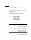
Reference for the Serial Port A and B
Connectors
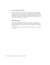
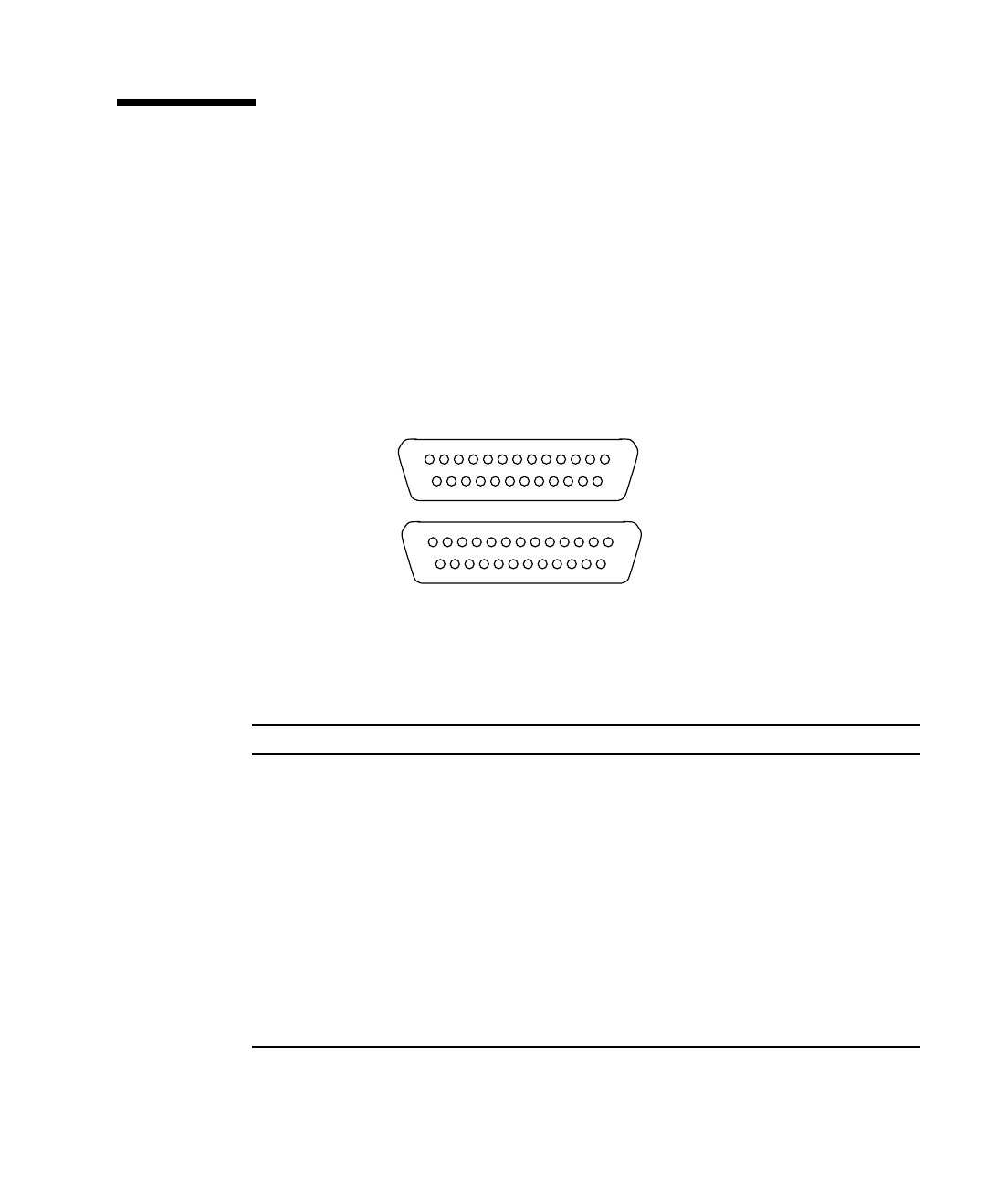
The serial port A and B connectors (J2902 and J2903, respectively) are DB-25 type
connectors located on the main logic board back panel. Both serial ports conform to
RS-423/RS-232 specifications.
Serial Port A and B Connector Diagram
Serial Port Signals
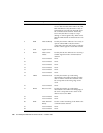
Pin Mnemonic Signal Name Description
1 Not connected None.
2 TXD Transmit Data Used by the data terminal equipment (DTE)
to transmit data to the data circuit
equipment (DCE). Except when control data
is being sent, RTS, CTS, and DCD must be
ON for this line to be active.
3 RXD Recieve Data Used by the DCE in response to received
data from the DTE.
4 RTS Ready to Send Used by the DTE to condition the DCE for
data transmission. The transition to ON
directs the DCE to go into transmit mode.
The transition to OFF directs the DCE to
complete the transmission.
113
25 14
113
25 14
Serial port B
Serial port A