


3-30 Ultra Enterprise 6000/5000/4000 Systems Manual—November 1996
3
3.5.5.2 Installing a Graphics (UPA) Card
1. Use the procedures described in Section 3.5.2, “Removing a Board,” to
remove the applicable Graphics I/O board.
Note – The connector pins on graphics (UPA) cards are extremely delicate, use
care when handling.
2. Attach a wrist strap and take the graphics (UPA) card out of the protective
packaging and place the card on an antistatic mat.
Inspect the pins in the connector to make sure they are not bent.
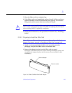
3. Remove the adapter bracket from the rear panel of the card.
See Figure 3-16. Remove the two screws securing the adapter to the card
rear panel (the adapter bracket and the screws are not needed for this
installation).
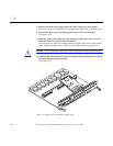
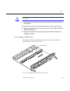
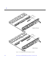
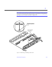
4. Locate the UPA connector for the card. See Figure 3-21.
5. If a filler panel covers the back panel slot for the graphics (UPA) card,
remove the two screws and detach the filler panel.
Retain the screws to attach the graphics (UPA) card to the back panel, unless
the card has a wide connector, or set of connectors.
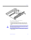
6. Unlock the two standoffs for the UPA connector slot.
See Figure 3-14.
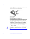
7. Hold the card at an angle and guide the card face plate under the
springfingers and against the rear face of the Graphics I/O board front
panel.
The I/O connectors of the card should be visible through the opening in the
I/O board front panel.
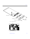
8. Hold the card by the edges nearest the UPA connector and position the
card over the two standoffs.
9. Hold the card by the edges near the connector and firmly but gently press
the card down until the connector is fully seated.
To align the connector and socket, push the card toward the Graphics I/O
board front panel.