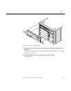
Non-Chassis Field Replaceable Units (FRUs) E-33
E
Note – Remember the proper orientation of the centerplane when removing it
from the front chassis.
13. Lift the centerplane out and set it aside.
To replace the centerplane:
1. Place the centerplane in the front chassis.
Be sure the centerplane has the proper orientation when placed in the front
chassis.
2. Replace the 20 screws that hold the centerplane to the front chassis.
3. Place the rear chassis on the front chassis.
4. Replace the 26 screws around the center of the main chassis.
5. Replace the feet on the bottom of the enclosure.
Screw in one foot in each corner.
6. Turn the enclosure over so that the feet are supporting the chassis.
7. Replace all boards and power supplies.
See Chapters 3-6 for information on replacing the boards and Chapter 7,
“Power Supplies,” for information on replacing power supplies.
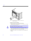
8. Replace the SCSI tray.
Tighten the bottom three captive screws and secure the SCSI tray to the
enclosure. See Figure E-18.
9. Replace the key switch assembly and the 100/240V fan tray assembly.
See Section E.2.2, “Key Switch Assembly and Section E.2.1, “Fan Tray
Assembly, 100V/240V” for information on replacing these assemblies.
10. Replace the top cover.
a. Slide the top cover over the key slots until it fits securely on the main
chassis.
b. Replace each plug.
11. Replace the side vents. Place each vent alongside the main chassis and
push the vent forward until it stops.


