


E-24 Ultra Enterprise 6000/5000/4000 Systems Manual—November 1996
E
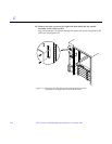
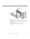
8. Loosen the four screws on each side of the system cabinet that attach the
top rails to the main chassis.
9. Remove the top rails and set them aside.
Guide the four screws through the key slots in each top rail.
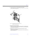
10. Remove the four screws on each side of the system cabinet that attach the
bottom rails to the main chassis.
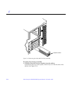
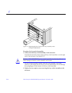
Warning – Use care when removing the Enterprise system chassis. It weighs
approximately 100 pounds.
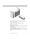
11. Carefully slide the Enterprise system chassis out toward the front and
place it front side down onto a surface.
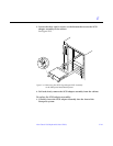
12. Remove the screws around the center of the main chassis.
• For the Enterprise 6000 system, there are a total of 32 screws, 8 per side.
• For the Enterprise 5000 system, there are a total of 26 screws.
13. Lift and remove the rear chassis and set it aside.
14. Remove the screws that hold the centerplane to the front chassis.
• For the Enterprise 6000 system, there are a total of 27 screws, 20 screws
around the side and 7 in the interior section.
• For the Enterprise 5000 system, there are a total of 20 screws.
Note – Remember the proper orientation of the centerplane when removing it
from the front chassis.
15. Lift the centerplane out and set it aside.
To replace the centerplane:
1. Place the centerplane in the front chassis.
Be sure the centerplane has the proper orientation when placed in the front
chassis.
2. Replace the screws that hold the centerplane to the front chassis.
• For the Enterprise 6000 system, there are a total of 27 screws, 20 screws
around the side and 7 in the interior section.
• For the Enterprise 5000 system, there are a total of 20 screws.
!