3-34 Ultra Enterprise 6000/5000/4000 Systems Manual—November 1996
3
3. Unseat the card from the I/O board:
a. Grasp the card underneath each corner on the end of the card that
connects to the I/O board receptacle (opposite the I/O board front
panel end), then firmly unseat the two standoffs and the card
connector.
b. Grasp the card underneath each corner near the I/O board front panel,
and then firmly unseat the remaining two standoffs from the I/O
board.
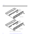
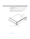
4. Once the card standoffs and connector are unseated, hold the card at a
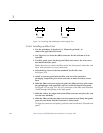
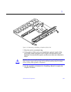
slight angle as shown in Figure 3-24 on page 3-33. Guide the card fiber
connector end from the front panel opening on the I/O board.
5. If the fibre card is not immediately replaced, install an OLC plug on the
I/O board front panel opening.
6. Use the procedures in Section 3.5.3, “Installing a Board,” to replace the
I/O board.
3.5.6.2 Installing a Fibre Card
1. Use the procedures in Section 3.5.2, “Removing a Board,” to remove the
applicable I/O board.
Note – If required, remove the OLC plug that protects the fiber optic connector
opening on the front panel of the I/O board. These OLC plugs are installed in
factory shipped systems without fibre cards installed.
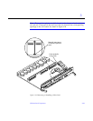
2. Locate the card slot for installation.
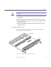
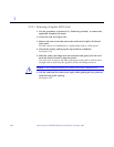
See Figure 3-23 on page 3-32. You may need to remove the SBus cards over
(or next to) this card to have enough room to hold onto the fibre card being
installed.
Note – There are four plastic inserts located on the bottom of each card, two on
each end of the card. These secure the card once they are inserted into
corresponding openings on the I/O board. See detail in Figure 3-24 on
page 3-33.


