


CPU/Memory Boards and Components 3-7
3
1. Ensure that the board has been disabled by the ASR software. See
Section 3.3, “Hot-Plug Feature.”
Once disabled by ASR, one of two results occurs:
• The three LEDs on the board are not lit (board has no power).
• The outer two green LEDs are not lit and the middle yellow LED is lit
(board in low power mode).
Note – System software operates such that the LED pattern described is the
same for a board that is component side down (installed in front of card cage)
or component side up (installed in rear of card cage).
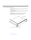
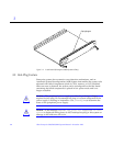
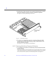
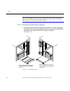
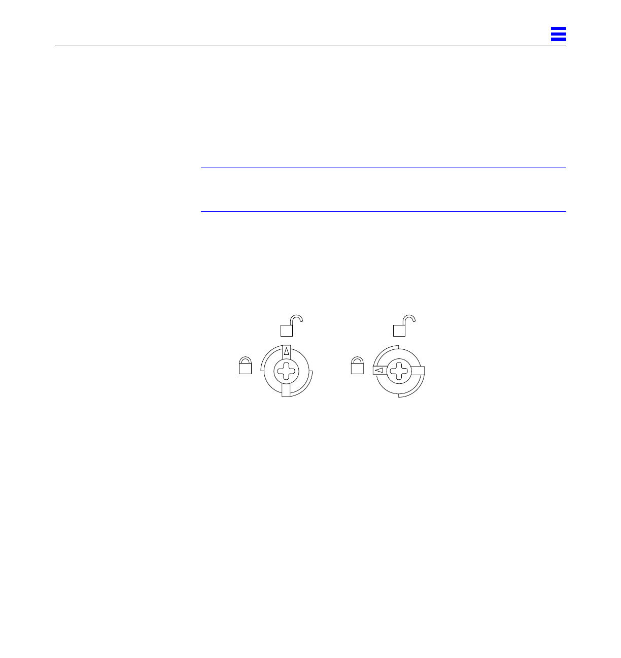
2. Use a Phillips #1 screwdriver to mechanically release the board from the
system card cage.
Insert the screwdriver into each quarter-turn access slot (the slots are located
on the left and right sides of the board front panel) and then turn a quarter
turn so that the arrow points to the unlocked position. See Figure 3-4.
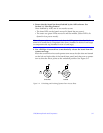
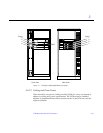
Figure 3-4 Unlocking and Locking Quarter-Turn Access Slots
Unlocked
Locked