Non-Chassis Field Replaceable Units (FRUs) E-31
E
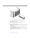
3. Tilt the top bezel at a 45
o
angle and insert the lip of the bezel under the
top of the enclosure.
See Figure E-16.
4. Lower the top bezel.
The top bezel should snap into place.
5. Replace the system key.
6. Power on the Enterprise system.
See the power on instructions in Chapter 12, “Powering Off and On.”
E.2.3 Centerplane
To remove the centerplane:
1. Completely power off the Enterprise system.
See the power off instructions in Chapter 12, “Powering Off and On.”
2. Remove the top bezel.
See Chapter 13, “Preparing for Service,” for information on removing this
assembly.
3. Remove the side vents. Push each side vent backwards until it stops. Then
lift the vent off the Enterprise system and set it aside.
4. Remove the top cover.
a. Locate the four plugs in each corner of the enclosure.
b. Lift each plug by pushing down in the dotted area.
This action causes the plug to pop up.
c. Remove each plug.
d. Lift up the front of the top cover and slide it backwards approximately
6-10 millimeters. Remove the top cover and set it aside.
5. Remove all the boards and power supplies.
See Chapters 3-6 for information on removing the boards and Chapter 7,
“Power Supplies,” for information on removing power supplies.


