


Troubleshooting Overview 9-5
9
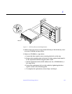
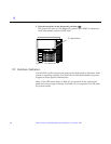
9.2.4 Disk Board LEDs
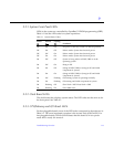
The board status LED codes correspond to those shown in Table 9-2 for the
CPU/Memory and I/O boards. The Disk board has two additional LEDs on
the opposite side of the board to show the status of the two onboard disk
drives. The LED for disk drive 1 is nearer to the side of the Disk board, and the
LED for disk drive 0 is closer to the center of the board.
9.2.5 Power Supplies
A system has one peripheral power supply and up to four or eight CPU/IO
modular power supplies. All the power supplies have one green LED and one
yellow LED.
The control and status signals of all power supply modules connect to the
clock board. If the clock board LEDs indicate a problem, inspect the LEDs on
the power supplies to locate a faulty module, if any.
9.2.5.1 Peripheral Power Supply
The green LED is to the right of the yellow LED on the peripheral power
supply. The green LED indicates that the peripheral power supply is operating,
but does not necessarily indicate that the DC outputs are within specification.
When the peripheral power supply module yellow LED is lit, a DC power
output has malfunctioned or the voltage level is out of specification.
The peripheral power supply produces +5 VDC and +12 VDC current. The
current is available for peripherals such as a tape drive and/or CD-ROM drive.
In addition, the +5 VDC output of the peripheral power supply is available at
the center plane for current sharing with the +5 VDC outputs of the power
supply modules.
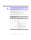
9.2.5.2 Power/Cooling Modules (PCMs)
For a PCM at the front of the card cage, the green LED is to the left of the
yellow LED. At the back of the card cage, the LED positions are reversed and
the green LED is to the right of the yellow LED. See Table 9-3.