


F-2 Ultra Enterprise 6000/5000/4000 Systems Manual—November 1996
F
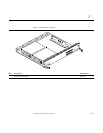
F.1 CPU/Memory Board
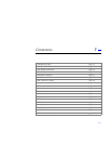
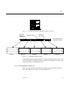
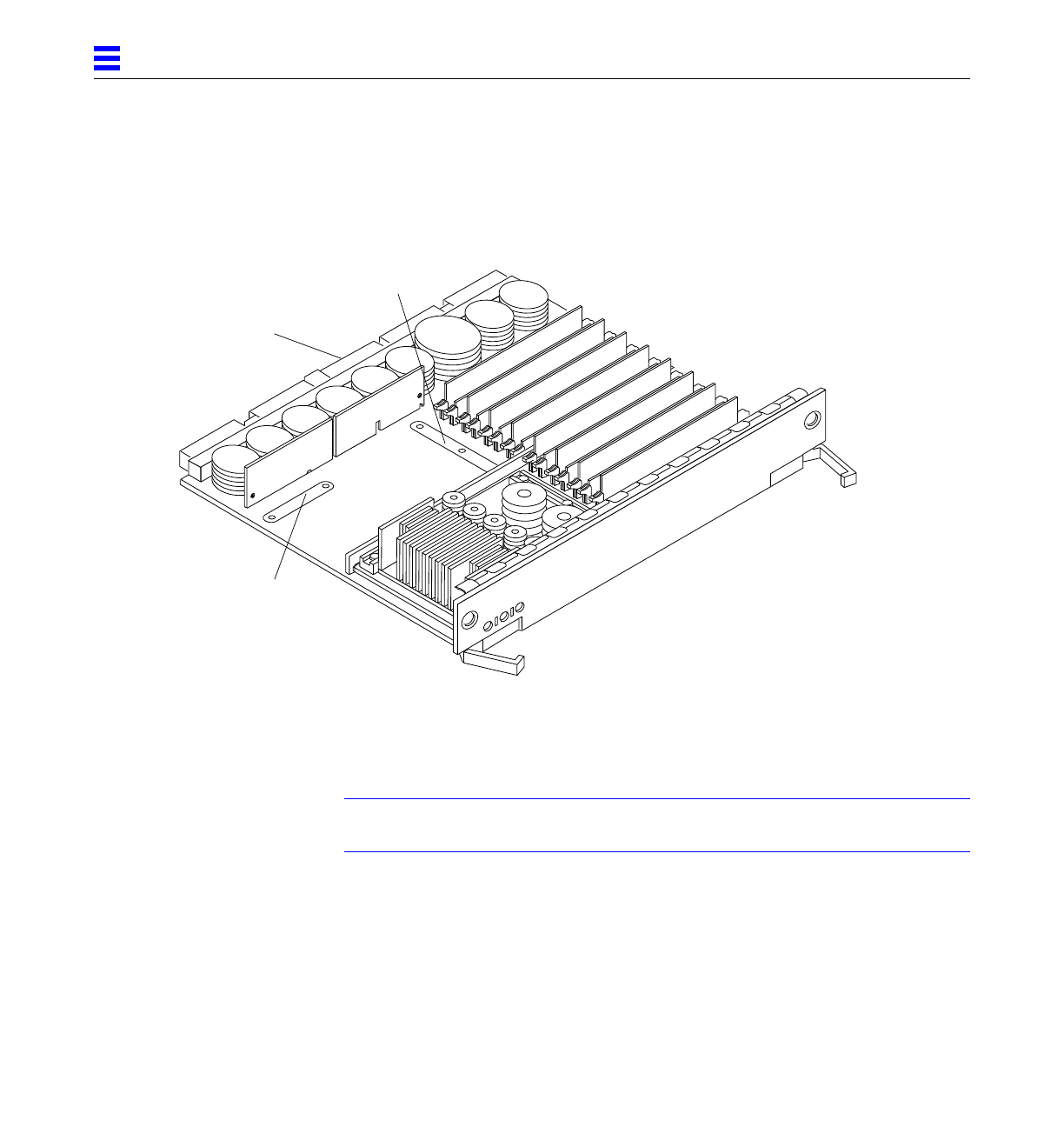
Figure F-1 shows the locations of the centerplane and CPU module connectors
for the CPU/Memory board.
Figure F-1 CPU/Memory Board Connector Locations
F.1.1 Centerplane Connector
Note – Information for the CPU/Memory board centerplane connector also
applies to the I/O and disk board centerplane connectors.
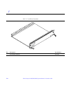
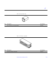
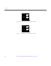
The CPU/Memory board centerplane connector is mounted on the rear of the
board, opposite the side of the board with the LED display and extraction
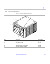
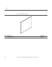
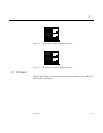
levers. See Figure F-2. The connector is comprised of modular sections, each
with its own set of receptacle pins. See Figure F-3.
Centerplane
144 pin
connector
288 pin connector
connector