


E-18 Ultra Enterprise 6000/5000/4000 Systems Manual—November 1996
E
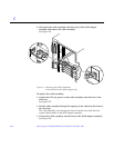
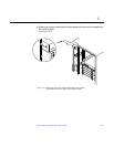
3. Replace the screw on the left side that attaches the key switch assembly to
the cabinet pillar.
See Figure E-10.
4. Connect the key switch cable assembly into the back of the key switch
assembly.
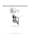
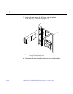
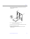
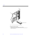
5. Replace the SCSI tray into the cabinet using the support system cabinet
CD shelf as a guide.
When seated properly, the SCSI tray is flush with the key switch assembly in
the cabinet. See Figure E-9.
6. Replace the two screws that attach the SCSI tray to the cabinet pillar.
See Figure E-8.
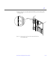
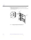
7. Replace the two screws that attach the SCSI tray to the flange on the side
of the fan tray shelf.
See Figure E-7.
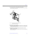
8. Connect the CD tray power and data cable assemblies into the back of the
SCSI tray.
See Figure E-5.
9. Replace the fan tray shelf cover.
Replace the 10 screws and attach the cover to the cabinet.
10. Replace the side panel closest to the key switch assembly.
See Chapter 13, “Preparing for Service,” for information on replacing the
side panel.
11. Power on the Enterprise system.
See the power on instructions in Chapter 12, “Powering Off and On.”
E.1.6 SCSI Tape Adapter PCS Assembly
To remove the SCSI adapter assembly:
1. Completely power off the Enterprise system.
See the power off instructions in Chapter 12, “Powering Off and On.”
2. Disconnect the two cable assemblies from the front of the SCSI adapter
assembly.
See Figure E-6.