


Functional Overview
WFM700 Series Waveform Monitors User Manual
2-5
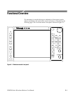
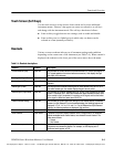
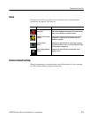
Touch Screen (Soft Keys)
Use the touch screen to select choices from a menu and to access additional
instrument menus. “Buttons” that appear on screen are referred to as soft keys
and change with the instrument mode. The soft keys function as follows:
H Some soft keys toggle between two settings, such as enable and disable.
H Some soft keys act as a linked group in which only one button can be
selected at a time (mutually exclusive).
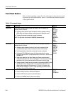
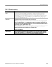
Readouts
Various on-screen readouts inform you of instrument settings and conditions,
depending on the current state of the instrument (see Table 2--4). When a menu is
displayed, the readouts on the lower part of the screen move above the menu.
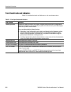
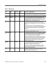
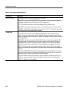
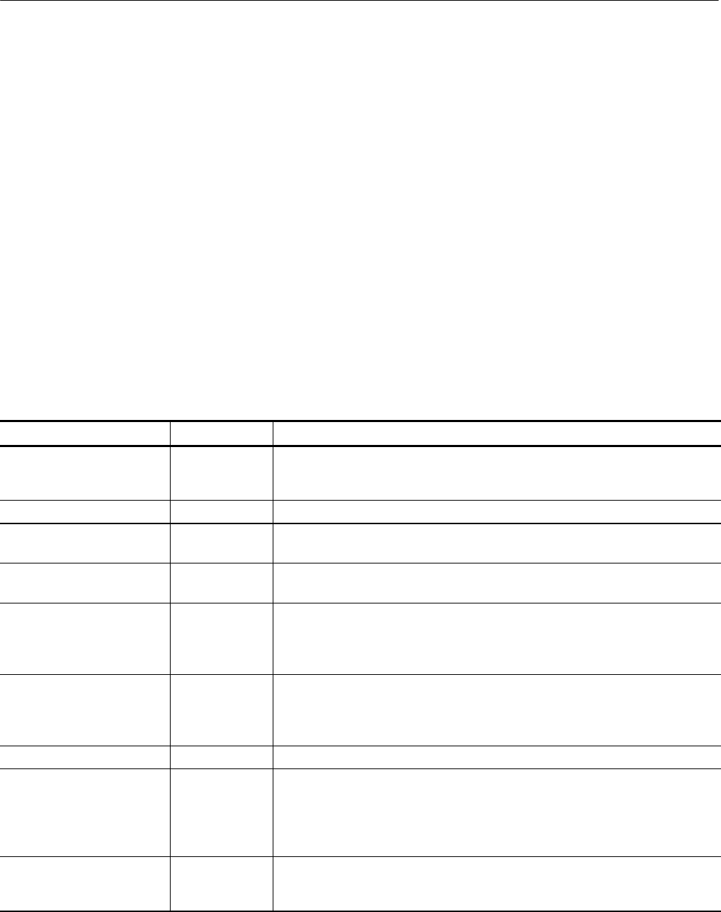
Table 2- 4: Readout descriptions
Readout Location Description
Current reference (Ref) Lower left Text indicates the current source of the video reference: INT (active i nput signal) or
EXT (signal applied on the ext ernal reference connector). Also displays the type
and status of the reference.
Vector graticule type (Bars:) Lower left Text indicates the current setting of the Vector Graticule, 75% or 100%.
Horizontal gain (HGain) Lower left Text displays the variable horizontal gain value in yellow to indicate that it is not
standard.
Vertical gain (VGain) Lower left Text displays which calibrated vertical gain you have selected, such as 1x or 5x. If
you select variable gain, the readout displays the gain value in yellow.
Selected input / input format Lower left Text indicates t he currently selected input (1A, 1B, 2A, or 2B), followed by the input
format. For example, 2A: 1.4835 Gb/s 1080sf:29.97 would indicate that the A input
of the module in slot 2 is selected, it is receiving an HD signal, and that the format
of the signal is 1080sf at a frame rate of 29.97 Hz.
Gamut threshold settings Lower left Text indicates the current gamut limit settings for the selected display: Arrowhead,
Diamond, or Split Diamond. For the Arrowhead display, the following readouts are
displayed: Y+C Hi, Y+C Lo, Y Hi, and Y Lo. For the Diamond and Split Diamond
displays, the following readouts are displayed: High and Low.
Color standard Lower center Text indicates the current colorimetry standard. Not present in all modes.
Audio channels Lower center If enabled in the Audio Displays submenu of the Configure menu, 16 characters
indicate embedded audio channel status; one character for each channel. The
codes are as follows:
P = Present
— = Not Present
Waveform components Lower center Text indicates the currently displayed waveform color components. Non-displayed
components are indicated by dashes. For example, an RGB display with G
deselected would appear as R--B.
Test Equipment Depot - 800.517.8431 - 99 Washington Street Melrose, MA 02176 - FAX 781.665.0780 - TestEquipmentDepot.com