


Functional Overview
2-10
WFM700 Series Waveform Monitors User Manual
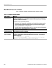
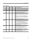
Table 2- 5: Rear-panel connectors (Cont.)
Connector(s) Description
Multi-pin connectors
The waveform monitor provides the following multi-pin connectors:
VGA PIX MON. A copy of the PIX G/Y, B/Pb, R/Pr pix mon outputs. This allows using an inexpensive
VGA monitor for non-critical HD applications. Most computer monitors will not lock to 50 Hz vertical rates
or to Standard Definition line rates, so this may not work in all applications.
EXT VGA. Provides an exact copy of the instrument display to drive an external monitor.
REMOTE. 9-pin subminiature D-type connector used as a Ground Closure interface for remote control.
ETHERNET. (10/100 Base T). 10/100 Mbit/sec Ethernet interface. Used for for web-based remote control
of the instrument and for downloading firmware upgrades.
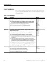
Coaxial Outputs
The waveform monitor provides the following coaxial outputs:
PIX G/Y, B/Pb, R/Pr. Provides three 75 Ω component signal outputs to drive a component picture
monitor. You can set the output format to YPbPr or RGB. Out of gamut input signals cause the affected
areas to be highlighted on the monitor display. This gamut error highlight or “bright-up” signal is controlled
in the Configure menu.
SD PIX MON. This output is a copy of t he PIX G/Y, B/Pb, R/Pr pix mon output, but is reclocked in SD
serial digital format. It is operational only for SD format input signals, and only while the SD signal is
being displayed on the screen of the waveform monitor. In addition, there is no signal output from this
connector on a module while an input signal from a second module is being displayed on the screen.
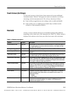
SERIAL OUT. Provides a version of the selected signal input (Video Input A or B). There is no signal
output from this connector on a module while an input signal from a second module is being displayed on
the screen.
JITTER OUT. (WFM700M only) Provides a 75 Ω output signal from the jitter dem odulator. This signal is
only valid when the instrument is in Jitt er mode. Any signal present on this output at other times is not a
calibrated jitter signal. The jitter filter sel ection does not affect this signal.
This signal is used as an input to an oscilloscope or spectrum analyzer to do additional analysis on the
jitter. You can view the same jitter wavef orm on the waveform monitor using the Jitter displ ay mode.
AUX OUT 1 / AUX OUT 2. Future capability.