


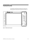

Functional Overview
WFM700 Series Waveform Monitors User Manual
2-9
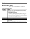
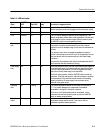
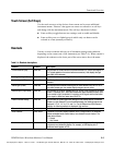
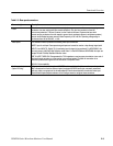
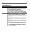
Table 2- 5: Rear-panel connectors
Connector(s) Description
Power
This instrument is intended to operate from a single-phase power source with one current-carrying
conductor at or near earth ground (the neutral conductor). Only the Line conductor is fused for
over-current protection. The fuse is internal, on the Power circuit board. Systems that have both
current-carrying conductors live with respect to ground (such as phase-to-phase in multiphase systems)
are not recommended as power sources. Mains frequency i s 50 or 60 Hz. Operating voltage range is
continuous from 100 to 240 VAC, ±10%.
Video inputs The waveform monitor provides the following video input connectors:
NOTE: Input A and Input B are separate signal inputs and cannot be used as a loop-through signal path.
INPUT A and INPUT B. Digital, 75 Ω terminating input for signal to be monitored. For WFM700HD, this
can only accept 1.485 Gb/s High Definition serial video. For the WFM700A and WFM700M, this input can
accept HD and 270 Mb/s Standard Definition video.
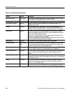
REF IN LOOP-THROUGH. Compensated for 75 Ω impedance; requires proper termination at one end of
the loop-through connector or at the receiver in a monitored system. Provides for connection of an
external synchronization signal such as black burst or composite video.
AUX IN. Future capability.
Audio inputs / outputs
(Option DG only)
When your instrument has the optional WFM7DG audio module installed, the waveform monitor provides
BNC connectors that function either as inputs for external AES/EBU audio (not necessarily associated
with any video) or as outputs of the de-embedded AES audio associated with the selected video input.
Use the Audio Inputs/Outputs submenu of the Configure menu to configure these connectors.